- Home
- Products
- CNC Slant Bed Lathe
- T55/T55L/T55M CNC Slant Lathe with High Accuracy
1 / 6
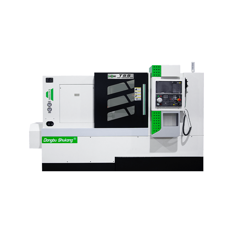
T55/T55L/T55M CNC Slant Lathe with High Accuracy
T55 Series CNC Slant Lathe Introduction
Maximum Machining Diameter: 300mm
Maximum Machining Length: 370mm
Chuck Size: 8" inch
TECHNICAL PARAMETERS
T55/T55L/T55M CNC Slant Lathe with High Accuracy — Description
T55 Series CNC Slant Lathe Introduction
It adopts a high-rigidity hydraulic servo turret, optimizes compensation through the servo system, and cooperates with the servo spindle to achieve multi-axis linkage. It can complete functions such as spindle positioning, rigid tapping, and curved surface milling, which greatly enriches the functions of the machine tool and improves the machine tool's performance. Adaptable to meet the processing needs of various types of parts.
1. The integrated hydraulic servo turret is compact and reliably precise.
2. The bed guideway adopts a high and low rail design and is integrally cast with resin sand. With multiple aging and heat treatment processes, the machine can maintain optimal precision and rigidity for a long time.
3. Hydraulic monitoring and adjustment can be easily operated using knobs on the front panel.
4. The ergonomic machine adopts 30° internal design, which makes the workpiece closer to the human body and facilitates chip discharge (rear or side chip discharge as needed).
Description of the basic structural features of the Lathe machine tool
1, Bed
The bed adopts an integrated high-low rail bed design, with a thick-walled, multi-ribbed, multi-cavity structure to ensure heavy cutting capabilities. The bed is cast with high-quality resin sand, with good rigidity, good shock resistance, and smooth chip removal.
2, Spindle box
The spindle bearings are designed with a combination of double-row short cylindrical roller bearings and double-direction thrust angular contact ball bearings. The servo main motor features stepless speed variation, achieving high torque and high rigidity, ensuring long-term precision stability during heavy cutting.
3, Feed system
The X and Z axis servo motors are directly connected to the precision ball screw through elastic couplings, with high precision. The two ends of the screw are fixed, which improves the support stiffness of the support seat, minimizes the distortion of the screw caused by frequent high-speed positioning and heavy cutting, and the bearings use 60-degree angular contact pairs of precision bearings for screws, with high speed and high precision.
4, Slide
The transmission adopts imported linear rolling guides from Taiwan to meet the requirements of high speed and high efficiency, reduce friction resistance and temperature rise deformation, improve processing accuracy, and ensure the long-term stability of cutting processing accuracy.
5, Turret
The machine is equipped with a high-rigidity hydraulic servo tool turret, which, through servo system optimization and compensation, works in conjunction with the servo spindle to achieve multi-axis interpolation. This enables functions such as spindle positioning, rigid tapping, and surface milling, significantly enhancing the machine tool's functionality and adaptability, thereby meeting the processing requirements of various parts.
6, Hydraulic system
In addition to program control, the clamping, loosening and telescopic extension of the hydr
Main Machine Components
| Headstock Improvements are made to the heat dissipation air duct and heat sink of the spindle headstock, reducing the temperature rise of the spindle box by 15%. Spindle Speed: 3000rpm Spindle Power: 11 kW Spindle Taper Hole: Φ62 mm | |
| Guideway of the Bed The bed guideway adopts the 30° high-low rail structure used in Japanese-style machine tools, ensuring the rigidity, precision, and stability of the machine during heavy-cutting operations. The automated loading and unloading unit (optional) is integrated with the machine, significantly reducing the floor space. X/Z-axis Travel: 190/400mm X/Z-axis Rapid Traverse Speed: 30/30m/min |
Configuration
| Standard Equipment | Optional Equipment |
|---|---|
| 1. SIEMENS 808D Advanced Control System | 1. FANUC 0i-TF Plus Control System |
| 2. A2-6 | 2. SIEMENS 828D Basic Control System |
| 3. Servo Spindle | 3. GSK 988TA Absolute Control System |
| 4. Hydraulic Through Chuck 8inch | 4. RENEISHAW Auto Tool Setter |
| 5. Hydraulic Servo 10 Tool Post Turret | 5. 12 Post Driven Tool Turret(BMT55) |
| 6. Hydraulic Tailstock | 6. Auto Bar Feeder |
| 7. Roller Linear Guideway | 7. Oil Skimmer |
| 8. Chip Conveyor |
T55 CNC Slant Lathe Specification
| Configuration | T55 | ||
|---|---|---|---|
| Machining Capacity | Maximum Swing Over Bed | φ/mm | 580 |
| Maximum Swing Over Slide | φ/mm | 300 | |
| Maximum Machining Length | mm | 370 | |
| Maximum Machining Diameter | φ/mm | 300 | |
| Maximum Diameter of Bar | φ/mm | 50 | |
| Servo Spindle | Spindle Head Type | GB59001 | A2-6 |
| Spindle Taper Hole | φ/mm | 62 | |
| Spindle Speed Range | r/min | 50-3000 | |
| Spindle Output Torque | N·m | 70 | |
| Main Motor Power | kW | 11 | |
| Chuck Type | Hydraulic Through Chuck | ||
| Chuck Size | inch | 8" | |
| Feed Rate | Rapid Traverse Speed On X-axis | m/min | 30 |
| Rapid Traverse Speed On Z-axis | m/min | 30 | |
| Servo Motor Torque On X-axis | N·m | 15 | |
| Servo Motor Torque On Z-axis | N·m | 15 | |
| X-axis Travel | mm | 190 | |
| Z-axis Travel | mm | 400 | |
| Guideway Type | Roller Linear Guideway | ||
| Turret | Turret Type | Hydraulic Servo 10 Tool Post Turret | |
| Tool Size | mm | 25×25/φ32(φ40 as optional) | |
| Tailstock | Tailstock Type | Hydraulic | |
| Tailstock Travel | mm | 320 | |
| Tailstock Sleeve Diameter | φ/mm | 74 | |
| Internal Taper of Tailstock Sleeve | MT5 | ||
| Power Source | Total Rated Power | KVA | 21 |
| Total Rated Current | A | 45 | |
| Dimension | Machine Weight | kg | 3700 |
| Machine Dimension | L*W*H(mm) | 2570×1820×1920 |
Appearance and parameters may slightly differ depending on the selected options.
T55L CNC Slant Lathe Machine Specification
| Configuration | T55L | ||
|---|---|---|---|
| Machining Capacity | Maximum Swing Over Bed | φ/mm | 580 |
| Maximum Swing Over Slide | φ/mm | 300 | |
| Maximum Machining Length | mm | 570 | |
| Maximum Machining Diameter | φ/mm | 300 | |
| Maximum Diameter of Bar | φ/mm | 50 | |
| Servo Spindle | Spindle Head Type | GB59001 | A2-6 |
| Spindle Taper Hole | φ/mm | 62 | |
| Spindle Speed Range | r/min | 50-3000 | |
| Spindle Output Torque | N·m | 70 | |
| Main Motor Power | kW | 11 | |
| Chuck Type | Hydraulic Through Chuck | ||
| Chuck Size | inch | 8" | |
| Feed Rate | Rapid Traverse Speed On X-axis | m/min | 30 |
| Rapid Traverse Speed On Z-axis | m/min | 30 | |
| Servo Motor Torque On X-axis | N·m | 15 | |
| Servo Motor Torque On Z-axis | N·m | 15 | |
| X-axis Travel | mm | 190 | |
| Z-axis Travel | mm | 600 | |
| Guideway Type | Roller Linear Guideway | ||
| Turret | Turret Type | Hydraulic Servo 10 Tool Post Turret | |
| Tool Size | mm | 25×25/φ32(φ40 as optional) | |
| Tailstock | Tailstock Type | Hydraulic | |
| Tailstock Travel | mm | 520 | |
| Tailstock Sleeve Diameter | φ/mm | 74 | |
| Internal Taper of Tailstock Sleeve | MT5 | ||
| Power Source | Total Rated Power | KVA | 21 |
| Total Rated Current | A | 45 | |
| Dimension | Machine Weight | kg | 4000 |
| Machine Dimension | L*W*H(mm) | 2770×1820×1920 |
Appearance and parameters may slightly differ depending on the selected options.
T55M CNC Slant Lathe Specification
| Configuration | T55M | |||
|---|---|---|---|---|
| Machining Capacity | Maximum Swing Over Bed | φ/mm | 580 | |
| Maximum Swing Over Slide | φ/mm | 300 | ||
| Maximum Machining Length | mm | 320 | 520 | |
| Maximum Machining Diameter | φ/mm | 300 | ||
| Maximum Diameter of Bar | φ/mm | 50 | ||
| Servo Spindle | Spindle Head Type | GB59001 | A2-6 | |
| Spindle Taper Hole | φ/mm | 62 | ||
| Spindle Speed Range | r/min | 50-3000 | ||
| Spindle Output Torque | N·m | 70 | ||
| Main Motor Power | kW | 11 | ||
| Chuck Type | Hydraulic Through Chuck | |||
| Chuck Size | inch | 8" | ||
| Feed Rate | Rapid Traverse Speed On X-axis | m/min | 30 | |
| Rapid Traverse Speed On Z-axis | m/min | 30 | ||
| Servo Motor Torque On X-axis | N·m | 15 | ||
| Servo Motor Torque On Z-axis | N·m | 15 | ||
| X-axis Travel | mm | 190 | 190 | |
| Z-axis Travel | mm | 350 | 550 | |
| Guideway Type | Roller Linear Guideway | |||
| Turret | Turret Type | 12 Post Driven Tool Turret (BMT55) | ||
| Tool Size | mm | 25×25/φ40/ER32 | ||
| Tailstock | Tailstock Type | Hydraulic | ||
| Tailstock Travel | mm | 320 | 520 | |
| Tailstock Sleeve Diameter | φ/mm | 74 | ||
| Internal Taper of Tailstock Sleeve | MT5 | |||
| Power Source | Total Rated Power | KVA | 21 | |
| Total Rated Current | A | 45 | ||
| Dimension | Machine Weight | kg | 3700 | 4000 |
| Machine Dimension | L*W*H(mm) | 2570×1820×1920 | 2770×1820×1920 |
Appearance and parameters may slightly differ depending on the selected options.