- Home
- Products
- CNC Slant Bed Lathe
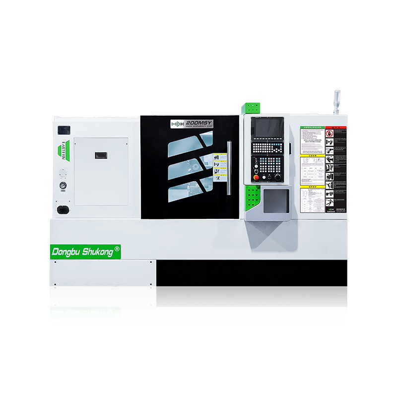
- 200MSY/200MSY With Sub-Spindle Y-Axis CNC Slant Bed Lathe
1 / 3
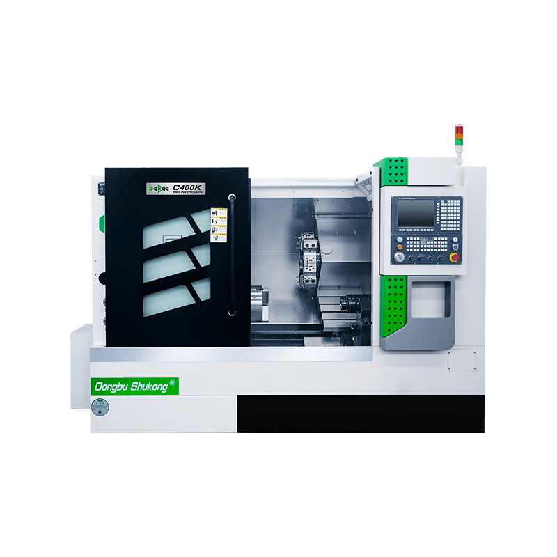
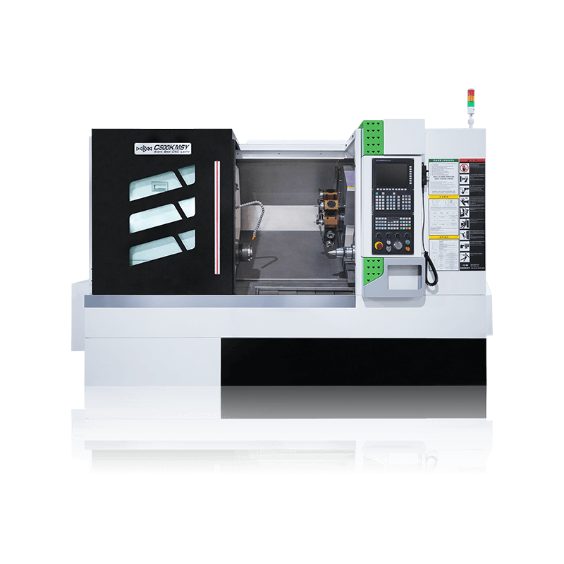
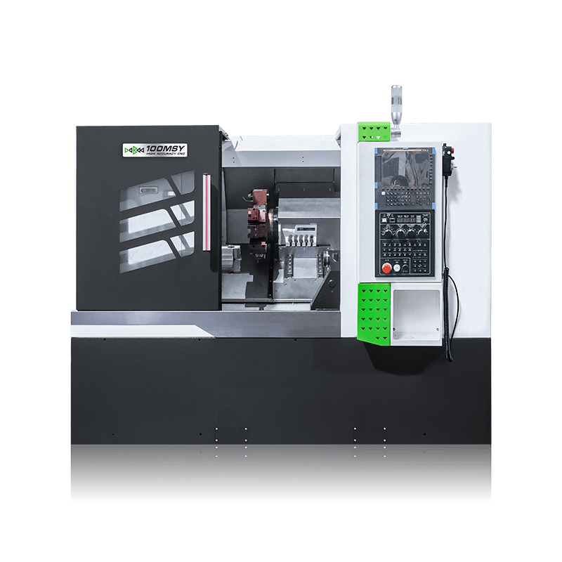
200MSY/200MSY With Sub-Spindle Y-Axis CNC Slant Bed Lathe
200MSY CNC Slant Bed Lathe Introduction
Maximum Machining Diameter: 360mm
Maximum Machining Length: 560mm
Chuck Size: 8" inch
TECHNICAL PARAMETERS
200MSY/200MSY With Sub-Spindle Y-Axis CNC Slant Bed Lathe — Description
200MSY CNC Slant Bed Lathe Introduction
The function of 200MSY/200MSY With Sub-Spindle CNC Slant Bed Lathe With Y-Axis is realized by a flat bed equipped with a 35º oblique interpolation Y-axis and a power milling turret. Multiple processes such as turning, milling, boring, drilling, tapping, and reaming can be completed in one clamping. It can reduce the number of clampings, improve processing accuracy, shorten the product manufacturing process chain, and improve production efficiency.
1. The high-rigidity Y-axis is realized through the movement of the middle (inclined) and large (horizontal) slides, which involves continuous two-axis interpolation. This enables milling operations with maximum rigidity.
2. The driven tool turret integrates the slide and utilizes a high-precision three-
Description of the basic structural features of the Lathe machine tool
1. Bed
L-shaped high-rigidity bed structure made of high-grade inoculated cast iron. Through FEM finite element structural analysis, the casting interior incorporates a large number of reinforcing ribs, optimizing the internal load-bearing structure of the entire machine and ensuring its rigidity and thermal field stability.
2. High-rigidity interpolation Y-axis structure
The upper and lower slides form a 35° inclined Y-axis structure, achieving high-rigidity Y-axis characteristics. The Y-axis is realized through the X-axis and a Y1-axis with a certain angle relative to the X-axis. The upper and lower bed saddles form a virtual Y-axis structure by interpolation on the high and low bed frames, with the Y-coordinate perpendicular to the X-coordinate. When the Y-coordinate moves, the X-axis and Y1-axis move simultaneously. This structure effectively overcomes the shortcomings of direct Y-axis structures, enhancing m
Main Machine Components
| Built-In Spindle The spindle is driven by a high-torque, high-efficiency, and high-performance permanent magnet synchronous motor. Additionally, P4 double-row short cylindrical roller bearings are adopted. This setup ensures the spindle's high precision, rigidity, and stability. Spindle Speed: 4000rpm Spindle Power: 18.5 kW Spindle Taper Hole: Φ62 Mm | |
| Integrated Driven Tool Turret The driven tool turret is characterized by high positioning accuracy, a compact design, and fast. It enables tool changes without lifting, thereby boosting machining efficiency. |
Configuration
| Standard Equipment | Optional Equipment |
|---|---|
| 1. SIEMENS 828D Basic Control System | 1. FANUC 0i-TF Plus Control System |
| 2. A2-6 | 2. SYNTEC 22TB Control System |
| 3. Built-in Spindle | 3. GSK 988TA Absolute Control System |
| 4. Hydraulic Through Chuck 8inch | 4. RENEISHAW Auto Tool Setter |
| 5. 12 Post Driven Tool Turret (BMT55) | 5. Auto Bar Feeder |
| 6. Servo Programmable Tailstock | 6. Oil Skimmer |
| 7. Roller Linear Guideway | 7. Chip Conveyor |
200MSY CNC Slant Bed Lathe Specification
| Configuration | 200MSY | 200MSY With Sub-Spindle | |||
|---|---|---|---|---|---|
| Machining Capacity | Maximum Swing Over Bed | φ/mm | 560 | 560 | |
| Maximum Swing Over Slide | φ/mm | 300 | 300 | ||
| Maximum Machining Length | mm | 560/800 | 560 | ||
| Maximum Diameter of Bar | φ/mm | 52 | 52 | ||
| Maximum Machining Diameter | φ/mm | 350 | 350 | ||
| Built-in Spindle | Spindle Head Type | GB59001 | A2-6 | A2-6,with Sub-Spindle A2-5 | |
| Spindle Taper Hole | φ/mm | 62 | 62, with Sub-Spindle 55 | ||
| Spindle Speed Range | rpm | 50-4000 | 50-4000, with Sub-Spindle 50-5000 | ||
| Spindle Shift Mode | Built-in Spindle | Built-in Spindle | |||
| Spindle Output Torque | N·m | 180 | Rated155/Max286,with Sub-Spindle Rated37/Max113 | ||
| Spindle Power | kW | 22 | 22, with Sub-Spindle 10.8 | ||
| Chuck Type | Hydraulic Through Chuck | Hydraulic Through Chuck | |||
| Chuck Size | inch | 8" | 8",with Sub-SpindleChuck 6" | ||
| Feed Rate | Rapid Traverse Speed On X-axis | m/min | 30 | 30 | |
| Rapid Traverse Speed On Y-axis | m/min | 10 | 10 | ||
| Rapid Traverse Speed On Z-axis | m/min | 30 | 30 | ||
| Rapid Traverse Speed On Z1-axis | m/min | 25 | —— | ||
| Servo Motor Torque On X-axis | N·m | 16.7 | 16.7 | ||
| Servo Motor Torque On Y-axis | N·m | 16.7 | 16.7 | ||
| Servo Motor Torque On Z-axis | N·m | 16.7 | 16.7 | ||
| Sub-Spindle Servo Motor Torque | N·m | —— | 8.34 | ||
| Servo Motor Torque On Z1-axis | N·m | 8.9 | —— | ||
| X-axis Travel | mm | 180 | 180 | ||
| Y-axis Travel | mm | +60 -40 | +60 -40 | ||
| Z-axis Travel | mm | 570/810 | 560 | ||
| Sub-Spindle Travel | mm | 500 | |||
| Z1-axis Travel | mm | 620/860 | —— | ||
| Guideway Type | Roller Linear Guideway | ||||
| Turret | Turret Type | 12 Post Driven Tool Turret(BMT55) | |||
| Tool Size | mm | 25×25/φ40/ER32 | |||
| Tailstock | Tailstock Type | Servo Programmable | —— | ||
| Internal Taper of Tailstock Sleeve | MT5 | ||||
| Tailstock Travel | mm | 620/860 | |||
| Power Source | Total Rated Power | KVA | 43 | ||
| Total Rated Current | A | 95 | |||
| Dimension | Machine Weight | kg | 4500/4820 | 4800 | |
| Machine Dimension | L*W*H(mm) | 2790X1900X1940/ 3030X1900X1940 | 2790×1900×1940 |
Appearance and parameters may slightly differ depending on the selected options.
200MSY CNC Slant Bed Lathe Specification
| Configuration | 200MSY(A2-8) | 200MSY(A2-8)With Sub-Spindle | |||
|---|---|---|---|---|---|
| Machining Capacity | Maximum Swing Over Bed | φ/mm | 560 | 560 | |
| Maximum Swing Over Slide | φ/mm | 300 | 300 | ||
| Maximum Machining Length | mm | 500 | 500 | ||
| Maximum Diameter of Bar | φ/mm | 85 | 85 | ||
| Maximum Machining Diameter | φ/mm | 350 | —— | ||
| Built-in Spindle | Spindle Head Type | GB59001 | A2-8 | A2-8,with Sub-Spindle A2-5 | |
| Spindle Taper Hole | φ/mm | 86 | 86, with Sub-Spindle 55 | ||
| Spindle Speed Range | rpm | 50-3000 | 50-3000, with Sub-Spindle 50-3500 | ||
| Spindle Shift Mode | Built-in Spindle | Built-in Spindle | |||
| Spindle Output Torque | N·m | Rate220 Max606 | Rated 200/Max606,with Sub-Spindle Rated37/Max113 | ||
| Spindle Power | kW | 26.5 | 26.5, with Sub-Spindle 10.8 | ||
| Chuck Type | Hydraulic Through Chuck | Hydraulic Through Chuck | |||
| Chuck Size | inch | 10" | 10",with Sub-SpindleChuck 6" | ||
| Feed Rate | Rapid Traverse Speed On X-axis | m/min | 30 | 30 | |
| Rapid Traverse Speed On Y-axis | m/min | 10 | 10 | ||
| Rapid Traverse Speed On Z-axis | m/min | 30 | 30 | ||
| Rapid Traverse Speed On Z1-axis | m/min | 20 | —— | ||
| Servo Motor Torque On X-axis | N·m | 16.7 | 16.7 | ||
| Servo Motor Torque On Y-axis | N·m | 16.7 | 16.7 | ||
| Servo Motor Torque On Z-axis | N·m | 16.7 | 16.7 | ||
| Sub-Spindle Servo Motor Torque | N·m | —— | 8.34 | ||
| Servo Motor Torque On Z1-axis | N·m | 8.9 | —— | ||
| X-axis Travel | mm | 180 | 180 | ||
| Y-axis Travel | mm | +60 -40 | +60 -40 | ||
| Z-axis Travel | mm | 500 | 500 | ||
| Sub-Spindle Travel | mm | 650 | |||
| Z1-axis Travel | mm | 620 | |||
| Guideway Type | Roller Linear Guideway | Roller Linear Guideway | |||
| Turret | Turret Type | 12 Post Driven Tool Turret(BMT55) | 12 Post Driven Tool Turret(BMT55) | ||
| Tool Size | mm | 25×25/φ40/ER32 | 25×25/φ40/ER32 | ||
| Tailstock | Tailstock Type | Servo Programmable | |||
| Internal Taper of Tailstock Sleeve | MT5 | —— | |||
| Tailstock Travel | mm | 620 | —— | ||
| Power Source | Total Rated Power | KVA | 43 | 43 | |
| Total Rated Current | A | 95 | 95 | ||
| Dimension | Machine Weight | kg | 4800 | 5100 | |
| Machine Dimension | L*W*H(mm) | 2790X1900X1940 | 2790×1900×1940 |
Appearance and parameters may slightly differ depending on the selected options.