- Home
- Products
- CNC Slant Bed Lathe
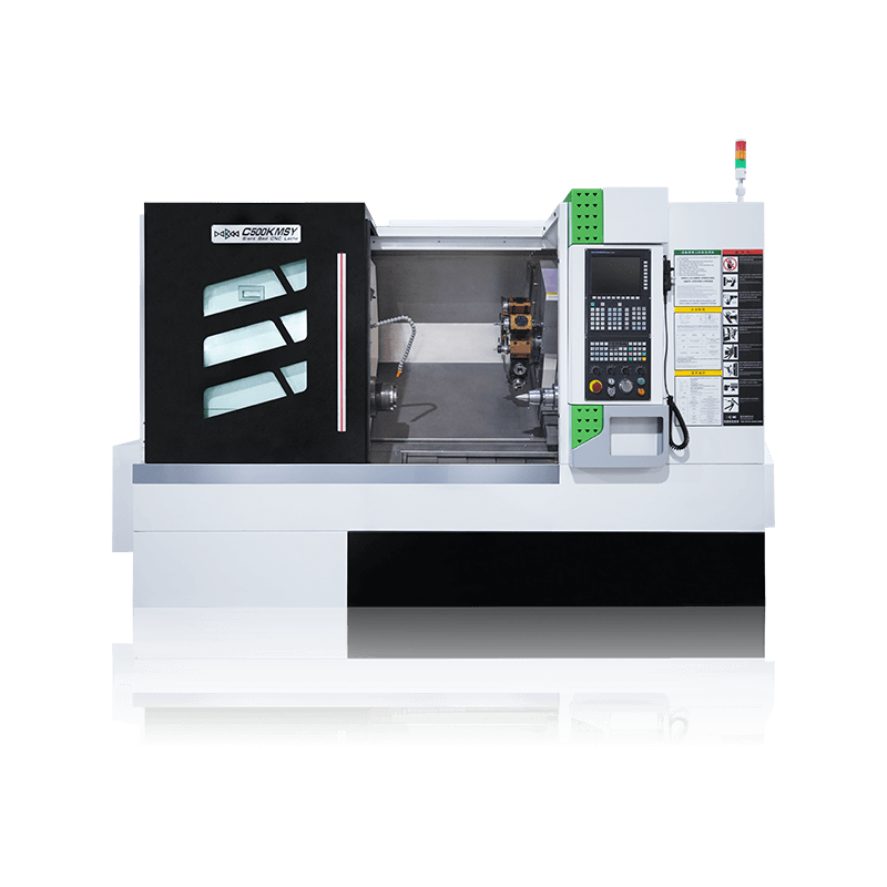
- C500K MSY/C500K/C500K With Sub-Spindle Heavy Cutting Slant Bed CNC Lathe
1 / 3
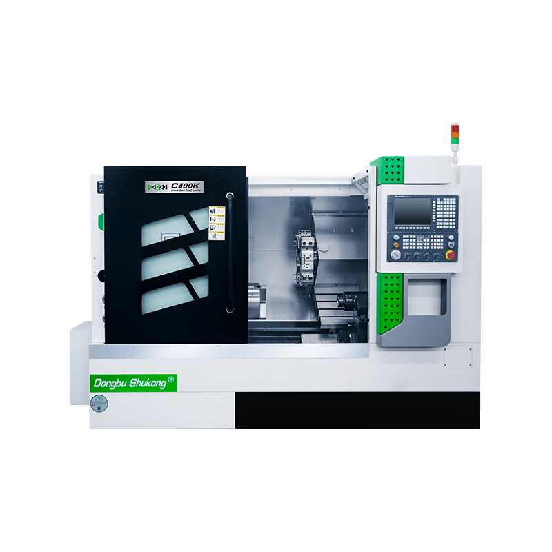
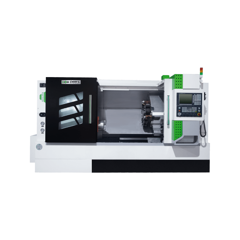
C500K MSY/C500K/C500K With Sub-Spindle Heavy Cutting Slant Bed CNC Lathe
C500K Slant Bed CNC Lathe Introduction
Maximum Machining Diameter: 430mm
Maximum Machining Length: 650mm
Chuck Size: 10" inch
TECHNICAL PARAMETERS
C500K MSY/C500K/C500K With Sub-Spindle Heavy Cutting Slant Bed CNC Lathe — Description
C500K Slant Bed CNC Lathe Introduction
The slant bed cnc lathe C500K series adopt an integrated 45° inclined bed and circular cavity cast iron structure to ensure heavy cutting capabilities. The bed is cast with high-quality resin sand, which has good rigidity, good shock resistance, and smooth chip removal.
The spindle box bearing adopts double-row cylindrical roller bearings and bidirectional thrust angular contact bearings, which have high rigidity. The heat dissipation adopts a corresponding structural design to reduce the thermal deformation of the spindle so that the spindle can maintain the relative stability of the spindle axis during long-term operation.
1. The lathe uses an hydraulic servo turret or Y-axis lifted driven tool turret with high positioning accuracy, fast tool cha
Description of the basic structural features of the machine tool
1 Bed
The bed features an integrated 45° slant bed circular cavity cast iron structure, ensuring heavy-duty cutting capability. The bed is cast using high-quality resin sand, offering excellent rigidity, vibration resistance, and smooth chip removal.
2 Spindle Housing
The spindle housing bearings utilize a combination of double-row cylindrical roller bearings and double-direction thrust angular contact bearings, providing high rigidity. The structural design incorporates measures to reduce spindle thermal deformation, ensuring the spindle maintains relative stability along its axis during prolonged operation.
structural design to minimize thermal deformation of the spindle, ensuring relative stability of the spindle axis during prolonged operation.
3 Feed System
The X and Z-axis servo motors are directly connected to precision ball screws via elastic couplings, offering high precision. The ball screws are fixed at bo
Main Machine Components
| Spindle The spindle box bearing features a structure of double-row short cylindrical roller bearings. This configuration enables it to achieve high precision and rigidity, thereby ensuring the long-term precision and stability during heavy-duty cutting operations. Spindle Speed: 2500rpm Spindle Power: 15kW Spindle Taper Hole: Φ86mm | |
| Headstock Improvements are made to the heat dissipation air duct and heat sink of the spindle headstock, reducing the temperature rise of the spindle box by 15%. | |
| Turret with Y-axis Function (Optional) It can significantly enhance the processing capability for complex workpieces and improve the processing accuracy of parts in multiple machining projects. The indexing of the cutter head is driven by a servo motor. Tool changing is executed in the nearest directions, featuring high speed and high efficiency. It has high positioning accuracy and repeat positioning accuracy, as well as high rigidity and stability. | |
| 35° Integrally Slant Bed Structure This structure ensures high stability and rigidity during the machine tool's operation, as well as the stability of mass-produced product quality. With multiple aging treatments, the stability and rigidity of the machine tool are significantly enhanced. |
Configuration
| Standard Equipment | Optional Equipment |
|---|---|
| 1. SIEMENS 808D Advanced Control System | 1. FANUC 0i-TF Plus Control System |
| 2. A2-8 | 2. SIEMENS 828D Basic Control System |
| 3. Servo Spindle | 3. SYNTEC 22TB Control System |
| 4. Hydraulic Through Chuck 10inch | 4. GSK 988TA Absolute Control System |
| 5. Hydraulic Servo 12 Tool Post Turret | 5. Built-in Spindle(C500K MSY) |
| 6. Hydraulic Tailstock | 6. Hydraulic Through Chuck 8 inch(C500K MSY) |
| 7. Roller Linear Guideway | 7. Hard Guideway/Linear Guideway(C500K MSY) |
| 8. Y-Aixs Lifed 12 Post Driven ToolTurret(C500K MSY) | |
| 9. RENEISHAWAuto Tool Setter | |
| 10. Auto BarFeeder | |
| 11. Oil Skimmer | |
| 12. Chip Conveyor | |
| 13. Servo Programmable Tailstock(Tailstock Travel: 600mm) |
C500K and C500KMSY Slant Bed Lathe Specification
| Configuration | C500K | C500K MSY | ||
|---|---|---|---|---|
| Machining Capacity | Maximum Swing Over Bed | φ/mm | 500 | 500 |
| Maximum Swing Over Slide | φ/mm | 300 | 300 | |
| Maximum Machining Length | mm | 650 | 550 | |
| Maximum Machining Diameter | φ/mm | 430 | 350 | |
| Maximum Diameter of Bar | φ/mm | 74 | 50 | |
| Spindle | Spindle Head Type | GB59001 | A2-8 | A2-6 |
| Spindle Taper Hole | φ/mm | 86 | 62 | |
| Spindle Speed Range | r/min | 60-2500 | 60-4000 | |
| Spindle Shift Mode | Servo | Built-in Spindle | ||
| Spindle Rated Torque | N·m | 220 | 180 | |
| Main Motor Power | kW | 15 | 17.2 | |
| Chuck Type | Hydraulic Through Chuck | Hydraulic Through Chuck | ||
| Chuck Size | inch | 10" | 8" | |
| Feed Rate | Rapid Traverse Speed On X-axis | m/min | 25 | 25 |
| Rapid Traverse Speed On Z-axis | m/min | 25 | 25 | |
| Servo Motor Torque On X-axis | N·m | 18 | 18 | |
| Servo Motor Torque On Z-axis | N·m | 18 | 18 | |
| X-axis Travel | mm | 240 | 190 | |
| Z-axis Travel | mm | 680 | 560 | |
| Y-axis Travel | mm | / | ±50 | |
| Guideway Type | Roller Linear Guideway | Roller Linear Guideway | ||
| Turret | Turret Type | Hydraulic Servo 12 Tool Post Turret | Y-Axis Lifted 12 Post Driven Tool Turret (BMT55) | |
| Tool Size | mm | 25×25/φ40 | 25×25/φ32/ER32 | |
| Tailstock | Tailstock Type | Hydraulic | Hydraulic | |
| Tailstock Sleeve Diameter | φ/mm | 100 | 100 | |
| Tailstock Sleeve Travel | mm | 80 | 80 | |
| Internal Taper of Tailstock Sleeve | MT5 | MT5 | ||
| Power Source | Total Rated Power | KVA | 26 | 26 |
| Total Rated Current | A | 50 | 50 | |
| Dimension | Machine Weight | kg | 5255 | 5300 |
| Machine Dimension | L*W*H(mm) | 3320×2000×2020 | 3320×2000×2020 |
Appearance and parameters may slightly differ depending on the selected options.
C500K with Driven Tool Turret Slant Bed Lathe Specification
| Configuration | C500K with Driven Tool Turret | ||
|---|---|---|---|
| Machining Capacity | Maximum Swing Over Bed | φ/mm | 500 |
| Maximum Swing Over Slide | φ/mm | 300 | |
| Maximum Machining Length | mm | 530 | |
| Maximum Machining Diameter | φ/mm | 430 | |
| Maximum Diameter of Bar | φ/mm | 74 | |
| Servo Spindle | Spindle Head Type | GB59001 | A2-8 |
| Spindle Taper Hole | φ/mm | 86 | |
| Spindle Speed Range | r/min | 60-2500 | |
| Spindle Shift Mode | Servo | ||
| Spindle Rated Torque | N·m | 220 | |
| Main Motor Power | kW | 15 | |
| Chuck Type | Hydraulic Through Chuck | ||
| Chuck Size | inch | 10" | |
| Feed Rate | Rapid Traverse Speed On X-axis | m/min | 25 |
| Rapid Traverse Speed On Z-axis | m/min | 25 | |
| Servo Motor Torque On X-axis | N·m | 18 | |
| Servo Motor Torque On Z-axis | N·m | 18 | |
| X-axis Travel | mm | 190 | |
| Z-axis Travel | mm | 535 | |
| Y-axis Travel | mm | / | |
| Guideway Type | Roller Linear Guideway | ||
| Turret | Turret Type | 12 Post Driven Tool Turret(BMT65) | |
| Tool Size | mm | 25×25/φ40/ER40 | |
| Tailstock | Tailstock Type | Hydraulic | |
| Tailstock Sleeve Diameter | φ/mm | 100 | |
| Tailstock Sleeve Travel | mm | 80 | |
| Internal Taper of Tailstock Sleeve | MT5 | ||
| Power Source | Total Rated Power | KVA | 26 |
| Total Rated Current | A | 50 | |
| Dimension | Machine Weight | kg | 5300 |
| Machine Dimension | L*W*H(mm) | 3320×2000×2020 |
Appearance and parameters may slightly differ depending on the selected options.
C500K with Sub-Spindle Slant Bed CNC Lathe Specification
| Configuration | C500K MS With Sub-Spindle | |||
|---|---|---|---|---|
| Machining Capacity | Maximum Swing Over Bed | φ/mm | 550 | |
| Maximum Swing Over Slide | φ/mm | 300 | ||
| Maximum Machining Length | mm | 480 | ||
| Maximum Diameter of Bar | φ/mm | 50 | ||
| Built-in Spindle | Spindle Head Type | GB59001 | A2-6 | |
| Spindle Taper Hole | φ/mm | 62 | ||
| Spindle Speed Range | r/min | 50-4000 | ||
| Spindle Shift Mode | Built-in Spindle | |||
| Spindle Rated Torque | N·m | 220 | ||
| Main Spindle Power | kW | 17.2 | ||
| Sub-Spindle Power | kW | 12.3 | ||
| Chuck Type | Hydraulic Through Chuck | |||
| Chuck Size | inch | 8",with Sub-Spindle Chuck 6" | ||
| Feed Rate | Rapid Traverse Speed On X-axis | m/min | 25 | |
| Rapid Traverse Speed On Z-axis | m/min | 25 | ||
| Servo Motor Torque On X-axis | N·m | 18 | ||
| Servo Motor Torque On Z-axis | N·m | 18 | ||
| X-axis Travel | mm | 240 | ||
| Z-axis Travel | mm | 500 | ||
| Sub-Spindle Travel | mm | 480 | ||
| Guideway Type | Roller Linear Guideway | |||
| Turret | Turret Type | 12 Post Driven Tool Turret (BMT55) | ||
| Tool Size | mm | 25×25/φ32/ER32 | ||
| Power Source | Total Rated Power | KVA | 43 | |
| Total Rated Current | A | 80 | ||
| Dimension | Machine Weight | kg | 5800 | |
| Machine Dimension | L*W*H(mm) | 3600×2000×2020 |
Appearance and parameters may slightly differ depending on the selected options.