Wiper insert in finishing turning: when it helps
A wiper insert in finishing turning doesn’t always help. We examine how it affects feed, surface roughness and vibration on serial parts.
Why finishing surface is not that simple
The process engineer almost always wants one thing: increase the feed and produce more parts per shift. But on the finishing pass this quickly impacts the surface. What works on the roughing pass becomes obvious on the finish.
A standard insert gives a clean trace only in a fairly narrow window of parameters. Slightly higher feed — the ridge grows. Slightly worse rigidity — a wave appears on the part. On paper the mode looks fine, but on the machine the margin is very small.
This is especially noticeable in a series. The first part after setup often looks good, sometimes too good. That makes it easy to decide the mode is already found. Then the insert wears a bit, temperature changes, the chuck grips the next blank differently, and the Ra margin quickly disappears.
Small things rarely remain small in finishing. A light vibration of the toolholder or the part, a long overhang, edge wear, built-up edge and unstable feed on a long pass all spoil the surface. Even if the dimension still holds, the surface can be out of tolerance. For serial parts this is unpleasant: the operator may not notice the issue immediately, and scrap accumulates fast.
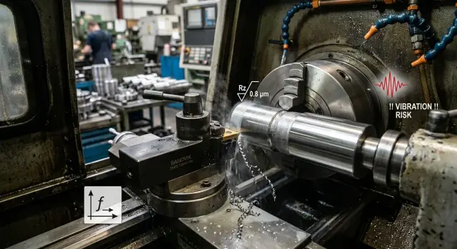
Vibration is even harsher. It does not hide on the finishing pass. Any tremor leaves a repeating trace, and the roughness gauge only confirms what the eye already sees. If the part is long, thin or protrudes from the chuck more than usual, the risk grows.
So the debate is not only about which Ra can be achieved. More important is this: can you hold that surface not just on one part, but across the whole batch? This is where interest in a wiper insert for finishing turning appears. It’s not about a cool idea, but about a wider working window where feed, surface and vibration risk don’t fight each other on every pass.
What a wiper insert does
A regular finishing insert leaves a wavy feed mark on the part. The higher the feed, the more pronounced that pattern and the faster roughness grows. A wiper insert has a longer, flatter cutting edge, so adjacent passes overlap more. This makes the surface smoother even without very slow cutting.
In practice the effect usually comes down to three things: a wiper insert smooths the feed trace better, often allows higher feed in the same operation, and at the same time requires a stiffer setup. The second point most often changes the economics of the cut. The operator keeps the same part, speed and depth, but increases feed by a step. In many cases roughness stays within tolerance and cycle time shortens slightly. In a series this becomes noticeable within a single shift.
There is also a simple visual effect. The surface looks more even: the feed step is less visible, light reflects more uniformly, and the part looks cleaner after the first pass. This is useful where the customer inspects shoulders, necks or bearing shoulders immediately.
But a wiper does not fix machine or fixture problems. If the carriage has play, the chuck grips poorly, the tool overhang is too long or the part starts to "sing", the new geometry won’t save it. Sometimes it even reveals weak spots faster, because the edge works over a larger area and reacts more sharply to poor rigidity.
You need to be realistic about this insert. It’s not magic — it’s a way to get a smoother surface at a higher feed if the machine, clamping and overhang are already in order. When the base is rigid, the difference is visible quickly. When the base is weak, fix the setup first, not the insert.
When it really helps
A wiper insert gives a noticeable effect where a regular finishing insert already hits a feed limit. In practice this shows not from a catalog, but from the cycle: the part meets roughness requirements without slowing the machine for a pretty surface.
The best case is a long series. If you turn tens or hundreds of identical parts, even a small increase in feed quickly adds up. A standard insert often forces cautious modes to hold Ra. A wiper allows a higher feed without losing surface quality. On a single part the gain may be modest, but over the whole batch it becomes clear.
The second condition is a rigid system. The blank must sit firmly, and tool overhang should be kept short. A wiper edge contacts more metal than a standard finishing geometry. If the machine, holder or part tend to oscillate, the wiper won’t save you. But on a rigid setup it often performs as expected: smoother surface, higher possible feed, and vibration risk under control.
Material also matters. Wipers work well where chips form cleanly without heavy built-up edge. If the material cuts cleanly, the insert leaves a predictable trace. Then it’s easier to maintain dimension and get consistent results part to part.
Another condition: the roughing pass must leave an even allowance. If the roughing operation left waves, variable stock or local bulges, the finishing cut starts in bad conditions. In that case the wiper won’t reveal its full potential because it has to correct the roughing’s consequences rather than simply smoothing the trace.
In short, wipers usually pay off where the series is large, clamping is rigid, overhang is short, the material doesn’t build up on the edge, and a regular insert is already at its Ra limit. It’s not a miracle, but it helps solve a clear problem: keep finishing turning stable without throttling feed unnecessarily. For serial parts this often matters more than any attractive catalog number.
When the benefit is minimal
A wiper insert does not save the process by itself. If the problem is rigidity, runout or uneven allowance, the difference often almost disappears.
A thin long part is the clearest example. If it already rings at a regular feed, trying to speed up for a wiper often only increases vibration. By calculation roughness should improve, but the part ends up with waves, marks and unpredictable Ra.
A similar picture appears when the chuck holds poorly or the blank has runout. Then the cutting edge works with variable load each revolution. Under such cutting even good geometry cannot produce a uniform surface because the tool is not cutting under consistent conditions.
A poor allowance after roughing also spoils results. If it’s torn, thicker in places and thinner in others, the finishing cut jumps. The edge alternately cuts normally, then rubs, then suddenly digs in. It’s better to level the roughing first than change the insert.
Weak results also occur where one insert is expected to do everything. After roughing the edge is already worn, sometimes with a small chip. Then the same insert is used for finishing and the comparison is unfair.
Another issue is materials that quickly build up edge. On gummy stainless, soft steels or some aluminum alloys the cutter behavior changes within a shift. Today the feed gives a clean surface, a few parts later a built-up edge breaks the forecast.
Usually benefit is small if the part already vibrates at ordinary modes, clamping is weak or there is runout, roughing leaves uneven stock, the same insert is used for roughing and finishing, or the material quickly forms built-up edge. In a series you’ll see it fast: first blanks still look acceptable, then scatter grows. In that situation fix the clamping, stock and mode first, and only then check whether a wiper insert is needed at all.
How to test it on your part
Test a wiper insert not on a "test rod" but on a real part from the current batch. That way you’ll see not a pretty one-off result, but what will happen during a shift: what feed holds, how roughness changes and whether extra vibration appears.
Start with a simple rule: change only one factor. If you change the insert and also material, allowance, holder or overhang, conclusions will be weak. You need an honest, comparable test.
Prepare two identical parts or two identical areas on one part. Use the actual production material. After roughing leave the same allowance for finishing. That’s important: a wiper usually shows best where modes and geometry don’t vary from part to part.
Keep test conditions identical: the same holder, same overhang, same cutting speed and same finishing depth. First run the regular insert, then the wiper.
Then raise feed stepwise, not in one big jump. For example, if the current feed is 0.12 mm/rev, test 0.12, 0.16 and 0.20 mm/rev. After each pass measure Ra in the same spot. If you have a long cylindrical surface, choose an area without grooves, chamfers or tool exit.
Watch not only the Ra number. Listen to the cut. If the next step brings a ringing sound, size drifts or the part shows ripples, that’s already the limit for your machine-holder-part combination. A wiper can give a better surface at higher feed, but sometimes vibration risk grows, especially on thin or long serial parts.
Record results after each step in one table: feed, Ra, size, sound and edge condition. Check wear with at least a loupe after a short series of several parts, not after a single pass. It’s easy to mistake a lucky first cut for a stable mode.
If the difference appears only on one part, that’s not enough. If the wiper holds the required roughness on 10–20 consecutive parts without extra noise and without accelerated wear, the test can be considered successful.
Mistakes that spoil conclusions
The most common mistake is simple: the operator changes everything at once. They raise feed, add spindle speed, touch depth, and then say the wiper "didn’t work" or, conversely, gave a great result. That comparison doesn’t work. If three parameters change, it’s unclear what actually affected the surface.
Equally common is comparing inserts with different nose radii. On paper this looks like testing two inserts, but in fact you compare two geometries at once. The conclusion becomes skewed: one insert supposedly holds feed better, while part of the difference came from a different radius.
To make the comparison fair
For a proper check fix almost all conditions: the same blank material, the same tool overhang, identical speed and depth, and the same measurement area.
There is a quieter mistake: looking at different places on the part. One area may be clamped more rigidly, another closer to the free end already vibrates. As a result one insert gets a favorable zone and the other a worse one. After such a test Ra numbers mean little.
On serial parts you cannot judge from the first piece only. The first part often comes out neat simply because the edge is still fresh, temperature hasn’t stabilized and chip flow is calm. By the tenth part the picture can change. If feed is chosen at the limit, the difference will show up there.
Another mistake is not addressing the fixture. Before the test many do not reduce the tool overhang even when they could. Then the machine picks up extra oscillation, and the insert geometry is blamed. If the holder protrudes too far, any finishing scheme will behave worse.
A good test looks boring, and that’s its advantage. Change one parameter at a time, measure the same area and check several consecutive parts. Then it becomes clear whether the insert helps on your serial parts or the effect was accidental.
A simple example on a serial part
Imagine a serial shaft made of steel 45. You must hold a diameter of 38 mm and get a surface no rougher than Ra 1.6 on the finishing pass. On such parts a wiper insert is interesting only if it gives either higher feed or less scrap.
With a regular insert the part runs fine at a feed of 0.10–0.12 mm/rev. Surface meets the requirement, dimension holds, but cycle time is longer than desired. If you raise feed to 0.18–0.20 mm/rev, cycle time drops, but Ra increases and the part needs more frequent checks or rework.
Use a wiper on the same part while keeping the same spindle speed, depth and finishing allowance. Then try 0.18 mm/rev. On a short overhang the result often looks like this: finishing time drops by about 20–30%, the surface stays within Ra tolerance, and the diameter doesn’t vary part to part.
This is the case where the insert really helps. There is no miracle — it simply provides a feed margin while the system cuts calmly.
But that margin disappears fast if the tool sticks out too far. On long overhangs small vibrations begin. Sometimes the operator hardly hears them, but the shaft already shows ripples and roughness measurement is worse than with a regular insert at lower feed. In that situation a wiper won’t save you. Trying to speed up simply eats the whole gain.
In practice decisions come down to two numbers: cycle time and scrap rate. If a regular insert gives 52 seconds per operation with almost zero scrap, and a wiper cuts cycle to 41 seconds without increased rejects, the choice is obvious. If cycle drops to 41 seconds but scrap rises from 1% to 4%, the savings are questionable.
For serial parts the conclusion is simple: compare not an insert alone, but the combination of feed, overhang, size stability and actual scrap per shift.
A quick check before launching a series
Before a series it’s better to spend 10 minutes checking than to sort a whole box of parts with varying roughness. For a mode with a wiper insert small things often decide everything: the same feed can give a smooth surface in a test and a visible trace on the batch.
First check the blanks, not the machine. If the trial pass used one batch of material, and a different batch goes into production, the result cannot be considered identical. Even a close grade can cut slightly harder or softer, changing the cutter trace and the sound during cutting.
Then check part setup. The chuck, jaws and references must hold the blank without noticeable runout. If the part pulls slightly, the operator may habitually blame the insert or feed even though the clamp is at fault. In a series this is especially unpleasant: the first two pieces still pass, then roughness starts to wander.
Another common mistake is long tool overhang. For finishing it’s best to keep overhang minimal. The farther the tool protrudes from the holder, the higher the risk of chatter, wavy trace and that unpleasant ringing after which the dimension may still be in tolerance but the surface is not.
Before launching a series quickly verify five things:
- blanks are from the same batch used in the test;
- the chuck and jaws show no significant runout;
- the tool has minimal overhang;
- the process engineer recorded modes on the card and the operator does not change them by feel;
- the shop knows which sound or trace requires stopping the machine.
Many underestimate the last point. If people haven’t agreed in advance, a series is stopped too late. It’s better to name simple signs up front: a whistle or ring appears, the surface develops an even wave, roughness rises on the first parts after changing blank or tool. This is not a reason to argue at the machine — it’s a reason to stop, check clamping, overhang and mode, then continue.
What to do next on the shop floor
Do not move a new mode into the series after one pretty part. A wiper insert’s normal start is a short test on 10–20 parts from the same batch, same material and same clamping. That way you see not a one-off good pass but real repeatability.
Watch more than roughness. Sometimes Ra improves, but the tool starts to wear faster or cycle time increases because the feed is too cautious. Such a trade rarely pleases when the batch is large.
Condense the check to four points: cycle time per part, Ra after the first parts and near the end of the test, insert wear and size stability, plus scrap rate, vibration traces and reworks.
If the wiper yields a cleaner surface at the same or higher feed, that’s a good sign. But decide only after the trial batch ends. For serial parts the gain must hold not just for two passes but until it’s clear how long the edge lives and how the size behaves.
When you can move the mode to production
Keep the mode if the picture is steady: cycle time didn’t increase, Ra doesn’t wander, the insert wears predictably and scrap does not rise. Even an 8–12 second saving per part gives a noticeable advantage across hundreds of pieces.
If the result jumps around, don’t rush to blame the insert. Often the issue is overhang, weak clamping, play, wrong feed or an old program where modes were written for another tooling geometry. One quick re-test after these fixes usually says more than arguing at the machine.
For shops in Kazakhstan and other CIS countries this approach is especially useful when selecting a CNC lathe for finishing. At EAST CNC, the official representative of Taizhou Eastern CNC Technology Co., Ltd. in Kazakhstan, you can get not only help selecting a machine but also support for launch: from consultation and supply to commissioning and service. This is important where a good mode must work not on a single test piece but across the whole series.