Wide Face Mill or Narrow Passes: Which Gives a Flatter Surface?
We explain when a wide face mill or narrow passes give a flatter surface on box-type parts, and how pass overlap changes the result.
What is the problem here
After face milling, the surface often looks good: the shine is even, the tool marks are neat, and the cutter path is clean. But then the part is set on a plate or checked with an indicator, and the picture changes. The middle sinks, the edge is tilted, and a small step appears between neighboring tracks.
The reason is simple: a nice cutter mark and good flatness are not the same thing. A surface can look clean, but during machining the tool bends a little, the part flexes, and clamping and heat change the shape even before measurement.
Why the eye gets it wrong
When face milling a surface, the eye notices shine and roughness first, not geometry. If the cutter removed metal without torn marks, the surface seems correct. But the indicator shows what the eye misses: a wave along the length, a dip over an internal cavity, or a height difference at the seam between passes.
This is especially common on box-type parts. The marks between passes may be almost invisible, yet the total flatness error is already outside tolerance.
Why a box-type part is trickier
A solid plate behaves more predictably: its mass and rigidity are distributed more evenly. A box-type part is different. It has cavities inside, thin walls and ribs nearby, and the metal thickness changes from one zone to another.
Because of this, the cutter is not cutting the same base across the full width. Over a cavity the part flexes a little; at the edge it holds less firmly. After the clamps are removed, the metal can release internal stress and the surface changes outside the machine.
Usually the problems show up in the same places. The edge ends up tilted because the tool enters and leaves the cut unevenly. A step remains between passes if the overlap is too small or the spindle is not set perfectly. Over windows and thin walls, a wave appears because the part is weaker there than over a rib or solid support.
So the choice between a wide face mill and several narrow passes is rarely about speed alone. First you look at how the part holds its shape under cutting and what the measurement will show afterward.
Two machining strategies
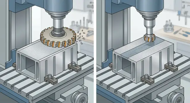
For the top surface of a box-type part, you usually choose one of two options. The first is a wide face mill that covers almost the full width in one pass or two close passes. The second is a smaller cutter and several neighboring tracks.
A wide cutter reduces the number of passes. There are fewer boundaries between tracks, and with them the risk of a visible step is lower. This setup is often faster too: fewer idle moves, a simpler toolpath, and less chance of building error from pass to pass.
Narrow passes split the stock removal into parts. The load on the tool, spindle, and part itself becomes lighter. On a box-type part, that is often useful: the walls and ribs move under cutting, and a calmer cutting mode can sometimes produce a flatter surface than one wide pass.
But several tracks bring another issue. Each next pass has to overlap the previous one. If the overlap is small, a ridge remains between passes. If it is too large, the cutter cuts again through an already finished strip, heat rises, and the finish changes. The surface may look smooth to the eye, but flatness can already drift by a few hundredths.
Diameter alone guarantees nothing. Runout, spindle rigidity, stick-out length, clamping, and even how evenly the inserts sit all affect the result. A large cutter on a weak setup can leave a wave. A smaller cutter in a calm setup can sometimes give a more truthful flat surface, even with more passes.
What changes when the part is box-shaped
A box-type part rarely behaves like a solid blank. From the outside it may look rigid, but inside it has windows, cavities, thin walls, and long spans between ribs. During face milling, this is felt right away: cutting force does not just remove metal, it also bends the top wall, especially if there is a void underneath it.
Clamping also changes the result a lot. If the housing is clamped at the edges or the supports are placed too far apart, the part is already sitting skewed on the table. The cutter then removes metal based on that distorted shape. After unclamping, the housing partly springs back, and the surface shifts.
There is another cause that is often underestimated: internal stress after casting, welding, or rough machining. While the part is clamped, those stresses are partly held back. After it leaves the table, one corner may lift, the center may return slightly, and differences appear between passes that were not visible on the machine.
A simple example: a housing has a top platform and a large cavity underneath it. If you place it on four corners and clamp it hard, everything looks stable from above. But during the pass, the center sags slightly. Once removed from the table, it springs back, and the measurement shows a different result.
What a wide cutter usually gives, and what narrow passes give
If you only look at the surface after machining, a wide face mill often wins. It covers the plane almost at once, the pattern is calmer, and there are fewer transitions between tracks. On a box-type part, this is especially noticeable.
But that strategy has a weak point. A large diameter reacts more sharply to spindle runout, part misalignment, and imperfect setup. If the cutter runs out even a little, the error is carried across the whole width of the pass. The surface may look neat, but flatness ends up worse than expected.
Narrow passes behave differently. They do not always give the same pretty pattern on the first try, but they are easier to adapt to the actual rigidity of the part. If the box sinks at the edge, over a window, or near a thin wall, the operator can change the step-over, allowance, or direction in that exact zone. With a wide cutter, there is less freedom: it loads a large area right away.
In practice, the difference usually comes down to a simple rule. A wide cutter hides the transitions between tracks better and often shortens the cycle. Narrow passes are easier to match to a flexible part, but they depend more on choosing the right overlap.
That point is often underestimated. If the tracks overlap too little, a ridge remains at the boundary. Sometimes it can barely be felt with a fingernail, but the indicator already sees the problem. On a box-type part, that ridge especially likes to appear near a window, a stiffener, or a section where the wall acts like a spring.
How pass overlap changes flatness
Pass overlap in milling directly affects whether a step remains between tracks. So when comparing a wide face mill and narrow passes, you need to look not only at the tool diameter, but also at how the neighboring passes overlap each other.
When the overlap is small, each next pass barely cuts the mark left by the previous one. On a box-type part, this is often visible right away: under angled light you can read the seam, and a feeler or indicator shows a local difference. The surface seems split into stripes.
Moderate overlap usually gives a calmer result. The cutter partly trims the ridge left by the neighboring track, and the transition becomes smoother. The step gets smaller, and flatness is often more stable across the full base length.
Too much overlap does not help either. The tool spends longer moving over already machined metal, and the cycle grows. On a thin top wall of a box-type part, that can create an unpleasant effect: right after machining the surface looks fine, but after cooling it shifts by a few hundredths.
There is another subtle point. The same overlap across the whole toolpath does not always give the same result near ribs, pockets, and windows. In a solid area the part holds firmly, but near a window the wall is weaker and can deflect a little. So the same step-over in the middle works well, but at the edge it leaves a mark.
The check is simple. After the first two passes, it is worth looking at the surface under angled light, comparing the seam in the center and near the window, and then measuring not just the overall flatness but also the local difference at the seam. Usually that is enough to see whether the overlap or the toolpath needs to change.
How to choose the strategy in practice
First, look at the part, not the cutter. If the box-shaped blank bends under clamping or is effectively hanging on two points, wide machining may give a nice mark but poor flatness after unclamping.
Setup matters a great deal here. If the supports are close to the edges and the middle is flexing, it is risky to pick a mode just by habit. You need to understand where the part really carries load and where it starts to move.
Before starting, it helps to check five things: the part rigidity and clamping force, the setup and support positions, the actual width of the surface, the real working width of the cutter, and a margin for a trial pass with inspection.
The working width is often misunderstood. A 100 mm cutter does not always cover 100 mm cleanly and consistently. Stick-out, insert position, runout, and entry into the material all matter. So compare the surface width not to the number in the catalog, but to how the tool cuts in real conditions.
If you are choosing between "a wide face mill or narrow passes," arguing in theory is pointless. It is much more useful to make a trial pass at the same spindle speed and feed planned for the batch, then check both the surface pattern and the measurement.
If waves appear across the whole width after a wide pass, the problem is usually rigidity or setup. If narrow passes leave visible stripes between tracks, the overlap is too small or the cutter is moving unevenly.
On a box-type housing, this is very practical. If the top surface is 140 mm wide and the cutter works steadily over 90–95 mm, it is often wiser to make two passes with proper overlap than to try to take the full width in one cut at the limit. If the part is short, rigid, and well supported, one wide pass can really give a cleaner and faster result.
An example on a box-type part
Imagine a housing with two large windows and a thin top band. A flat reference surface is needed on top for a cover. At first glance the part seems rigid, but near the windows the metal holds load worse, and the band can easily move by a few hundredths.
First, a 125 mm wide face mill is used to machine the plane in one fast pass. The center looks clean, and the cycle time is good, but near the window another picture appears. The thin area flexes slightly under cutting, and the edge ends up lower than the rest of the plane. On measurement this does not look like a rough dip, but like a smooth drop at the edge, for example 0.03–0.05 mm.
Then the strategy is changed. A 63 mm cutter is used, and the surface is machined in several passes with about 25–30% overlap. The stock removal per pass is smaller, the load on the thin band is gentler, and the part behaves more calmly. A light mark remains between passes at first, but the next pass cleans it up.
Yes, the cycle becomes longer. But the batch runs more consistently: less random variation, fewer arguments with inspection, and a lower risk that the edge near the window will drop again. For such housings, several narrow passes are often more honest than one wide pass, even if the surface does not look quite as pretty.
Mistakes that most often ruin the result
On box-type parts, flatness is usually ruined not by the strategy itself, but by small setup mistakes.
The first common mistake is using too wide a face mill on a part that lacks rigidity. The top wall and the areas over cavities do not behave like a solid plate. While the part is clamped, this may be hard to notice. After unclamping, the surface shifts.
The second mistake is choosing too little overlap between passes and expecting perfect geometry. On paper there are fewer passes and the cycle is shorter. On the machine, a height transition remains between tracks, especially if the setup is only moderately rigid.
The third mistake is looking only at the surface pattern. That is a trap. A beautiful finish is not the same as good geometry. When face milling a plane, you need to check not only the appearance, but also the flatness along at least several lines, not just one point.
Another mistake is changing feed without checking tool runout and the clamping setup. If one tooth is cutting harder than the others, the holder is running out, or the clamp is pulling the housing sideways, the cutting mode will not save you. First check the spindle, tool, stick-out, and supports, and only then adjust the feed.
And one more costly detail: the part is measured immediately after machining, while it is still warm. The metal is still moving, especially on box-type housings with different wall thicknesses. A short pause before the final measurement often gives a more honest picture.
Checking before starting production
Do not rely on one good part. Before production, make a trial cut on one or two blanks and watch not only the size, but the flatness itself.
The most useful check is simple. Run an indicator along the edges and around the internal windows. Compare neighboring passes by the surface pattern. Check the seam where the passes change: the boundary between tracks is often easier to feel with a fingernail than to see with the eye. After removing the part from the table, measure the flatness again. If everything was fine under clamping but the shape shifted after unclamping, the cause is in the clamping setup and internal stresses.
It is also useful to compare both the first and the last part from a short trial batch. If the spread grows, the cause may be heat, buildup on the inserts, zero shift, or a change in clamping force.
If the seam between passes shows up near a window or at the outer edge, it is better not to start the batch right away. Often one adjustment is enough: slightly change the overlap, reduce tool stick-out, or move the clamp. That is cheaper than reworking the batch.
What to do next
The question of what is better — a wide face mill or narrow passes — should be answered by measurement, not habit. Take a trial part or two identical blanks, machine the surface using both strategies at similar settings, and compare not only the appearance, but also flatness, the step between passes, and how the part behaves after unclamping.
Look at the same points: the center of the surface, areas over walls and ribs, the edges, and the zones near windows. That is usually where you can see whether pass overlap in milling smooths the surface or leaves marks between passes.
To make sure the conclusion is not accidental, it helps to write down the pass width, overlap percentage, depth of cut, feed, and flatness control points right away. After a few days, these details are easy to forget, but they are exactly what saves time later in production.
If the part is weak, it is not worth chasing the fastest cycle. Thin walls, large windows, and a long surface usually react more strongly to load than to one extra minute of machining. In that case, the strategy should be chosen for stability and repeatability.
If you need help choosing a machine for this kind of work or want a more practical view of machining setup, you can look at EAST CNC materials. The company works with supply, installation, and service of CNC lathes for manufacturing businesses in Kazakhstan and CIS countries, and its blog publishes equipment reviews and metalworking tips.
The next good step is simple: make one trial, take measurements, compare both strategies, and keep the one that gives stable flatness on your part.
FAQ
When does a wide face mill actually give a flatter surface?
A wide face mill is usually the better choice when the part is rigid, sits well on supports, and the surface can be covered in one pass. In that case there are fewer seams between passes, so the chance of a noticeable step is lower. If the body is thin or the supports are poor, one wide pass often gives a nice-looking finish but not the flattest surface.
When is it better to choose several narrow passes?
Several narrow passes are often better for box-type housings with windows, thin walls, and long spans between ribs. This loads the part more gently and gives you better control over the problem areas. The cycle is usually longer, but the surface after unclamping is often more honest and stable.
What overlap should be used as a starting point?
For a starting point, people usually choose moderate overlap, about 25–30%. That is often enough for the next pass to trim the ridge left by the previous one without overheating the already finished strip. If the overlap is too small, a step remains at the seam. If it is too large, heat and machining time increase.
Why does the surface look good but the indicator shows deviation?
Because the eye notices shine and texture, not geometry. The cutter can leave a clean-looking track, but at that moment the part may already be flexing a little because of cutting force, clamping, or heat. An indicator shows what the eye misses: a wave along the length, a dropped edge, or a height difference between adjacent passes.
Where do the biggest flatness errors usually appear on a box-type part?
The surface usually goes off near windows, above cavities, by thin walls, and along the outer edge. There the metal holds the load less well, and the top wall flexes more easily under the cutter. Those are the places where it helps to check not only the overall flatness, but also the local difference at the pass seam.
What should be checked first: the cutter or the clamping setup?
First check the clamping and supports. If the body sits at an angle or the middle is hanging, no cutter diameter will save the result. After that, look at runout, stick-out, insert seating, and the cutting mode. In practice, poor setup ruins the result more often than the pass strategy itself.
How can you tell overlap error from tool runout?
If the seam repeats exactly along the pass boundary, the overlap or the height difference between passes is usually the issue. If the wave runs across the whole width and is not tied to the seam, look for runout, a weak setup, or a twisted part. It helps to compare the center of the surface and the area near the window. That makes it easier to see where the error starts.
Should flatness be measured right after milling?
It is better not to rush. Let the part cool a little, then do the final measurement, especially if the body is thin and the walls are not the same thickness. Right after machining the metal can still change shape, and you may get an overly optimistic reading.
How do you properly check the machining setup before starting a batch?
Make a trial cut on one or two blanks at the same speed and feed you plan to use in production. Then compare not only the appearance, but also the flatness at the edges, in the center, and near the windows. If the shape shifts after unclamping, do not change the program numbers blindly. Check the supports, clamping, or the pass strategy instead.
What should be done if the edge near a window keeps dropping after machining?
Usually the fix is to reduce the load on that area. People often switch to a narrower cutter, reduce the depth of cut, change the machining direction, or use passes with proper overlap. Also check how the part sits on the supports. If the edge is hanging or the clamp is pulling the body, the drop will keep coming back.