When to Ask the Client for a 3D Model and Not Waste Time
When to ask a client for a 3D model and when a drawing is enough: where the shop loses hours, when the risk of scrap grows, and what to check before launch.
Why the 3D model question comes up too late
It usually starts the same way. The client sends a PDF, asks for a quick lead time, and expects the run to start without extra questions. The drawing looks clear, dimensions are neatly shown, and the part seems familiar. The manager sees a routine job and the shop doesn’t want to delay approval.
Problems appear later, when the technologist opens the documentation before programming. That’s when it becomes clear that a flat drawing doesn’t show everything unambiguously: where a fillet starts, how planes meet, the exact shape of a pocket bottom, how a thread exits, or from which datum to measure depth. Over the phone these places often sound “clear.” When you need to build a toolpath, that clarity is gone.
On paper the debate “drawing or 3D model” doesn’t seem so serious. In the shop it quickly becomes lost hours.
If the part has a simple outline, work proceeds without delay. But on housing parts one ambiguity is almost never the only one. Each guess leads to another, and every assumption affects machining.
Time is usually lost in three places:
- the technologist redraws the shape manually from views and sections;
- the programmer makes assumptions where an exact profile is needed;
- the operator notices a mismatch after the first operation or during inspection.
The worst-case scenario is surprisingly ordinary. A housing with threaded holes and a complex internal transition: the PDF lists dimensions but it’s unclear where a fillet begins or how the thread exits into a blind zone. The shop reconstructs the geometry by guesswork, writes the program, machines the first part, and only then discovers the tool removed too much material in the transition. The thread is offset relative to the seating surface and the part must be reworked almost entirely.
That’s why the 3D model question is often raised too late. During estimating ambiguities remain hidden. Once real preparation for the run begins, any inaccuracy turns into lost time, tools and material.
The more complex the shape, the more expensive an "we’ll figure it out" attitude becomes. In metalworking that’s a bad bet.
When a drawing is enough
If the part consists of simple planes, holes, slots and straight pockets, a good drawing is usually sufficient. A 3D model doesn’t always add value in such cases. Sometimes it’s just another file to reconcile.
The format itself doesn’t solve anything. Clarity does. If the drawing immediately defines datums, dimensions and tolerances, the technologist quickly understands how to set the part, where to measure from and what to check after machining.
A drawing is usually enough when:
- the reference surfaces are obvious at first glance;
- dimensions do not contradict each other;
- threads are fully specified: standard, pitch and depth;
- the shape does not require freeform surfaces or complex transitions;
- the client answers one or two precise questions quickly.
This set works well for common housing parts where geometry can be built from views and sections. If walls are straight, holes are located by coordinates, and pockets have simple shapes, the shop won’t spend time modeling. That is enough to start.
The rule for threads is simple: the drawing must contain all the data with no omissions. Markings like M10 or G1/4 don’t help if depth, lead-in, thread length or tool exit location are unclear. When those data are present, the programmer doesn’t guess and can write the operation right away.
The same goes for the part shape. If there are no variable fillets, unclear blends or transitions that are hard to read from two views, the drawing closes the task completely. In practice such a set is often more convenient than a hastily assembled model without clear dimension logic.
A simple example: a housing with a datum plane, two locating holes, a pocket with straight walls and four M8 threads to 16 mm depth. If datums are clear and the client quickly clarified which side to measure the thread depth from, the part can be prepared for production without a 3D model.
A good guideline: if after reviewing the drawing the technologist has one or two precise questions—not a long list of assumptions—the drawing is usually enough.
When it’s better to request a model immediately
Decide this before calculating machining time, not after the first disputed operation. If the technologist or programmer can only see the shape by guessing, the shop almost certainly will lose hours on clarifications, rechecks and trial builds.
On a simple part the drawing is enough. On a housing part everything can change fast. One pocket cuts into another, a window intersects an internal shelf, and the top view seems ordinary while the 3D shape is already ambiguous.
Request a 3D model right away if:
- there are pockets, windows and ledges that intersect each other;
- the part contains many threads of different types, pitches or depths;
- fillets blend into one another and it’s hard to see boundaries on the drawing;
- there are inclined planes and dimensions come from multiple datums;
- the shape cannot be confidently reconstructed from available views and sections.
The issue is not just convenience. When a shop engineer rebuilds the shape from the drawing, they in effect make design decisions. Sometimes that goes fine. Other times a single guess shifts a hole, changes a pocket depth, or breaks assembly logic.
The risk is higher with threads. A drawing may show a designation, but it’s not always clear where the lead-in begins, what tool overhang is required, whether there’s a chamfer before the thread, or how close neighboring features are. If complex transitions or small radii sit nearby, the error arises not in the NC code but earlier—in the understanding of the geometry.
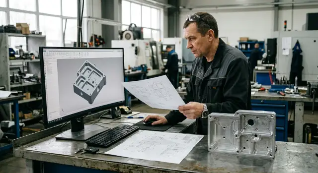
What a 3D model gives at the start
A 3D model doesn’t replace the drawing, but it removes disputed points quickly. The technologist sees the shape as a whole, the programmer builds the toolpath without extra assumptions, and the setup team doesn’t spend a shift checking things that could have been clarified in ten minutes.
This is especially useful when the part references multiple datums. From a single drawing it’s easy to mix up which datum an inclined plane, a hole or a pocket depth should be measured from. The model shows that immediately.
If the team has more than two or three questions about the shape after the first look, don’t let the shop build the part by trial. It’s better to request the client’s model and fix disputed points before launch than to argue later because of scrap or unnecessary rework.
Where time is lost in the shop
Most time is burned not on actual machining but before the first run. The machine is ready and people are present, yet the part isn’t brought to a clear geometry.
First the technologist reconstructs the shape from views, sections and auxiliary elements. On a simple bushing this takes minutes. On a housing with pockets, windows, ledges and multiple datums the work easily stretches to hours because you have to rebuild the volume, not just read the drawing.
Then programming slows down. If a fillet is missing, the thread exit is unclear, or a surface transition is ambiguous, the programmer checks each sheet, raises notes, asks the technologist questions, and builds a temporary version just to test the toolpath logic.
Time is usually spent on four things:
- the technologist draws what is not explicitly shown;
- the programmer searches for missing dimensions and transition shapes;
- quality control finds inconsistencies between sheets;
- the team adjusts the toolpath after the first check.
Each loop seems small, but together they consume a shift. Sometimes more. Threads are especially painful: pitch may be specified but lead-in length is unclear; a thread is shown in one view but not in section; the tool exit is guessed during machining.
Complex transitions make even more noise. If a housing has fillets, inclined walls and several intersecting surfaces, one inaccuracy in reconstruction changes the toolpath, cutting depth and even tool selection. After the first check the team often stalls not because of a code error but because the baseline geometry turned out to be different.
The most costly pause is quiet: the machine simply waits for the client’s answer. While the manager clarifies a disputed dimension or asks for a model, the schedule slips. For the shop that’s worse than an obvious breakdown because people and equipment are occupied waiting instead of working.
If the part is complex, a 3D model often saves not minutes but an entire cycle of approvals.
How to settle the question before the run
It’s better to close the issue when the technologist first opens the client’s package, not after the first setup. If the 2D doesn’t give an unambiguous shape at first glance, don’t guess. It’s easier to pause for 15 minutes and clarify disputed points than to lose a shift on rework.
A practical rule: anything that cannot be read unambiguously from views, sections and cross-sections should be marked immediately. This applies to hidden cavities, complex fillet transitions, shaped cuts, nonstandard thread exits, and places where a surface changes shape in a non-obvious way.
Next, separate sizes that are critical for running the part from reference notes. If a dimension affects datum setup, fit, pocket depth, hole position, transition profile or a thread, it’s a working dimension. If it only duplicates geometry already given and helps reading the drawing, don’t turn it into a separate question.
Before start, a short action list is enough:
- mark elements that 2D does not fully describe;
- list only the working dimensions and tolerances;
- ask precise questions for each disputed node;
- request the model in the native format or as a STEP file;
- lock a single working file version for the shop.
How you phrase the request also speeds replies. Instead of "send 3D model," write: "We need the model because the transition between the pocket and the threaded hole is not readable on the drawing." Clients respond faster when they see a concrete reason.
This is especially visible on housings with multiple threads and intersecting cavities. One team reviews the PDF, the programmer opens a STEP, and the shop foreman uses an older file from a message thread. In the end the dispute is no longer about the part but about who saw which file.
A simple sign: if the team starts to invent the shape, one drawing is already insufficient. It’s better to send one precise request before the run than to correct errors in the shop later.
Example: housing with threads and complex transitions
Imagine a housing part for a cover assembly. On the drawing everything looks calm: overall sizes, datums, main holes and seating dimensions. From the first views that seems enough.
The problem is hidden inside. Two pockets must meet in one area but are read differently from different views. One technologist will model a smooth filleted transition, another will leave an almost straight web. Formally both interpretations can be derived from the drawing, but the toolpath, machining time and final shape will differ.
With the cover thread confusion is usually greater. The sheet shows diameter and pitch, but run-out, lead-in length and thread exit are described too briefly. For machining this matters. If the thread lead-in is too short, the cover may screw in tightly or not seat. If undersize is guessed, the assembly may bind against an edge and produce scrap on final inspection.
Where time is lost
Usually no one stops the job immediately. The programmer builds a disputed shape, then checks sections, discusses it with the setter and only then writes to the client. Half a day can easily go on one such part, and that time is spent not on machining but on guessing the designer’s intent.
Worse: the error can end up in the first part. Externally the housing appears in tolerance, while internally there’s excess material, the tool won’t reach, or the thread assembles with force. Rework later costs noticeably more than one precise request before the start.
What a ready 3D model changes
A ready model settles disputes before the first operation. The technologist immediately sees how pockets meet, where the thread starts, what run-out is needed and what transition is intended between surfaces. The program can be built faster and QC gets a clear geometry for inspection.
On such parts it becomes clear when you should ask the client for a model. If there are intersecting cavities, a short thread run-out, or complex transitions, one drawing is not enough. The drawing stays the main document, but without the model the shop starts inventing the part rather than manufacturing it.
Common mistakes when working with a client
Problems often start not in the shop but in the correspondence. The contractor writes: “Need 3D model,” but doesn’t explain what exactly is in question. The client sees a general request, finds any suitable file and sends the fastest match. Time is lost and clarity doesn’t improve.
If the doubt is about one feature, name it directly: the thread exit for M12 is not readable, the fillet in the transition is unclear, or the pocket depth is ambiguous. A specific question almost always resolves faster than asking for the entire project archive.
Another mistake is using a render or presentation image as working geometry. A nice picture shows the external shape only. It can’t reliably verify internal cavities, chamfers, transitions, fits and small features. For production you need a model from which geometry can be extracted, not an image for appearance approval.
Also be careful not to compare the model with an older drawing. The client may have revision 03 while the shop receives an old STEP from revision 01. Externally the part may look similar, but one thread may already be different, one hole shifted by 2 mm, and the whole preparation goes astray.
Take verbal changes cautiously. If the client says on a call: “Make this 14 instead of 12,” that isn’t enough. Any change must be fixed in a file: an updated drawing, a new model, or at least an email with a revision number. Otherwise in a week everyone remembers the change differently.
What to clarify right away
Before launch agree on four things: which file is primary, which revision is current, which dimensions are mandatory for machining and inspection, and which threads are informative vs. required to meet exactly.
Thread confusion happens constantly. One note on the drawing may be informational while a technologist treats it as mandatory. On housing parts this quickly becomes scrap, especially if a complex transition, countersink or short tool exit is nearby.
A working rule: if there is at least one disputed spot, don’t accept guesses. Five minutes of clarification saves machine hours and removes disputes after the run.
Short checklist before start
Five minutes of checks before launch often save a day of rework. On housing parts mistakes are rarely single: a datum shifts, a pocket is misread, the wrong thread is chosen, and the whole chain goes off.
First open the drawing and model side by side. Datum names should match without any “well, that’s obvious.” If the drawing sets datum A for fixturing but the model names the bearing plane differently or not at all, the programmer and setter may read the part differently.
Then go through the threads. Verify not only diameter but standard, pitch and depth of each thread. A note like M12 alone doesn’t help if one side expects a fine pitch and the other a coarse one.
Don’t guess on complex transitions. If the part has fillets, radii, grooves, wall blends and bottom details, the shape should read the same in the drawing and the model. When you see only “about like this,” the shop again reconstructs the geometry itself.
Before start check five points:
- do datums and coordinate systems match;
- is each pocket clear without verbal explanation;
- are all threads fully specified: standard, pitch, depth;
- is each transition shape clear, not just the overall outline;
- is the team working from a single file and a single part name.
The last point is often underestimated. If the designer sent “final_3,” the technologist saved “final_3_new,” and the shop used an old file, error is almost guaranteed. Better to assign one working file in advance and avoid multiple parallel versions in correspondence.
If there is still a question on any of these points, the drawing is not enough. In that case request the model before starting while the cost of an error is still small.
What to do next
Don’t postpone the decision until the part is already on the schedule and the technologist has started resolving disputed areas. If questions remain about the housing, threads, pockets, radii or transitions, compare time: how long will it take to request a model from the client versus how long it will take to build the disputed node in-house. On simple parts the drawing is often enough; on housings one inaccurate guess can eat half a day.
If you’re still deciding when to ask the client for a 3D model, use a simple test: can you understand the geometry and prepare the part for the run without assumptions? If not, don’t rebuild the entire model for order. Sometimes it’s faster to request only a STEP file or a 3D model for the specific area at risk.
It helps to set a short working procedure. Before putting the part in the schedule set a deadline for the client’s reply on the model or clarifications. If the deadline doesn’t suit, remove the part from the nearest run rather than leave it hanging. Keep your own list of cases where a model is almost always needed: housing parts, intersecting holes, nonstandard threads, and complex surface transitions. Add to that list after each disputed order based on real time losses.
This approach reduces arguments between the technologist, programmer and production. The team stops guessing the client’s intent and reaches the run faster without rework.
If such parts occur regularly, discuss not only the file set but also the machining route in advance. EAST CNC, the official representative of Taizhou Eastern CNC Technology Co., Ltd. in Kazakhstan, helps with selecting CNC machines, commissioning and service for metalworking tasks. That’s especially relevant for housing parts, 5-axis machining and complex geometry where the cost of an unclear source part quickly becomes too high.
FAQ
When is a drawing enough without a 3D model?
A drawing is enough when the part’s shape can be understood without guessing. If datums are clear, dimensions don’t contradict each other, and holes, pockets and threads are fully specified, the shop can prepare the run without a 3D model.
What signs mean I should request a 3D model right away?
Request a model up front if there are intersecting pockets, inclined planes, complex fillets, or multiple datums. The same applies to threads when the PDF doesn’t clearly show lead-in, depth or tool exit.
Why does a PDF often delay the start?
A PDF often doesn’t show the part’s volume unambiguously. While a manager estimates lead time this may not be obvious, but during programming any ambiguity becomes questions, revisions and machine downtime.
What usually can’t be read from a 2D drawing?
Most often people misread transitions between surfaces, the shape of a pocket bottom, fillet boundaries, and thread details. Two views may look clear, but when building the toolpath the exact geometry is missing.
Can the shop just reconstruct the model itself?
The shop can rebuild the shape itself, but then it effectively decides for the designer. On a simple part that sometimes works, but on a housing part it’s easy to shift a hole, change a transition, or remove too much material.
What if the issue is only with one area of the part?
If the doubt is only about one feature, don’t ask for the whole project. It’s faster to request a STEP or 3D model of that area and specify exactly what is unclear on the drawing.
How to correctly ask the client for a 3D model?
Be short and specific: name the element and explain why you can’t confidently start without a model. For example: the transition between the pocket and the threaded hole is unclear, or the thread exit isn’t shown.
How to ensure the model and drawing are the same revision?
First check revision numbers and file names. Then open the drawing and the model side by side and verify datums, holes, threads and disputed transitions so the team isn’t working from different versions.
Where does the shop lose most time without a 3D model?
It’s not only the programmer’s time. The team spends hours on clarifications, trial builds, rechecking dimensions and correcting the first toolpath while the machine waits.
How quickly decide if a model is needed or not?
Look at the number of assumptions. If the technologist has one precise question left, the drawing is usually sufficient; if there are many questions about the shape, stop and request a model before starting.