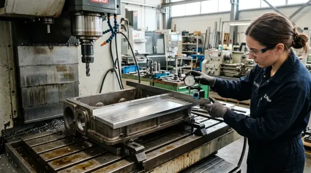
Wedge after milling long seating surfaces
A wedge after milling long seating surfaces usually stems from fixturing, part heating and the milling pass strategy.
What is a wedge on a long plane
A wedge on a long seating surface appears when one end of the surface ends up higher and the other lower. On the drawing it should be one flat plane, but after milling it acquires a gentle slope along its length. This is not an isolated pit or a random bump but a stable form error.
From the outside the part often looks fine. Tool marks are even, surface roughness acceptable, edges clean. But inspection shows the plane does not hold one level along the whole length. This defect is usually found by measurement: with a feeler and a straightedge, a dial indicator run along the surface, or a measurement map from several points.
The picture is almost always the same. In one zone the size may still be within tolerance, but then the deviation gradually increases. Sometimes the difference is only a few hundredths of a millimeter, but on a long base that's enough for the part to behave incorrectly in assembly.
On housing parts this defect is especially unpleasant. A seating surface sets the position of a cover, guide, support or another assembly. If one edge of a gearbox housing sits higher than the other, the cover initially contacts only part of the surface. Bolts then pull it down and the assembly settles with a skew.
Bolts can clamp parts together, but they do not fix the geometry. Contact spots change, coaxiality of adjacent surfaces is lost and local loading increases. Sometimes the problem doesn’t appear immediately but after startup: extra noise, heating or accelerated wear may show up.
The worst part is that even a small wedge has a noticeable effect on a long part. The longer the plane and the tighter the fit, the sooner the error shows up in assembly. So a wedge after milling should not be treated as a minor issue.
Where the tilt comes from
A tilt rarely has a single cause. Usually several factors coincide: the part is supported incorrectly, clamping slightly bends the housing, and the cutter heats one zone more than another. As a result the plane looks neat after the pass but slopes along its length.
A common cause is incorrect datum points. Long seating surfaces are hard to machine accurately if the housing rests on random spots, a casting skin or an already deformed surface. On the machine the part is in one position, and after unclamping it adopts another. On the table everything looked fine, but in inspection height drift appears.
Clamping also causes many problems. If a clamp presses next to a thin wall or on a weak bottom of the housing, it doesn’t just hold the part but pulls it. During cutting this may be almost invisible. After unclamping the metal partially springs back, and the plane is no longer correct. On a long housing even small deformations easily turn into a noticeable tilt at the end of the base.
Heat works against accuracy too. If the cutter spends a long time cutting one area, makes extra idle moves, or plunges into material overloaded, that area heats more. The metal expands unevenly. While the part is hot the size may look normal, but after cooling the geometry shifts.
Another source of the problem is varying stock allowance along the length. When more material is left at one end, the cutter removes it under higher load. The other end cuts more easily. Cutting forces change during the pass and the plane ends up at different heights. This is often seen after roughing, when the allowance noticeably varies.
Finally, the tool matters. A worn cutter cuts unevenly: one segment of the circumference still cuts cleanly while another rubs, heats and drags the surface. The mode may look the same, but the result differs each time.
If you sum it up simply: a wedge appears where the datum, clamping, heat and load do not match each other. Sometimes a single weak point is enough for a noticeable defect to grow along a long plane.
How to fixture a housing part without tilt
A wedge after milling often starts not with the cutter but with how the part is set up. If the housing sits on a chip, burr or uneven support, the finishing pass only locks in the error.
First you need to clean everything involved in fixturing: the table, prisms or supports, the part’s lower datums and the clamps. Even a thin chip under one support can change seating by tens of microns. For a long seating surface that is enough.
It’s useful not just to place the housing on supports but to check how it actually sits. After a light seating by hand look for rocking. If the part moves even slightly, one of the supports is not working properly or the housing rests on the wrong points.
After that use an indicator to record the part’s initial position along the length. Check it both before and after clamping. That immediately shows what the clamps do: hold the housing or pull one edge down.
How to clamp without excess deformation
Put clamps closer to the stiff zones of the housing: ribs, bosses, thickenings, and areas near internal partitions. If you press on a thin wall or a long span without support, the housing changes shape even before milling begins.
A good clamping scheme is simple. First seat the part on supports with little force. Then check the start, middle and end of the base with an indicator. Only after that tighten clamps one by one in small increments, each time checking that the line along the length has not shifted.
If the housing is long, one center measurement is not enough. The tilt often hides at the edges. Better to run the indicator the whole length and immediately see the moment when the part begins to bear on an edge.
Before the finishing pass it helps to make a trial cut with a shallow depth and then measure the plane again. If the geometry has already shifted, the cause is almost always the seating or the clamping scheme, not the finishing cutter. This short check saves both time and parts.
How heat pulls the plane
A long seating surface often goes to a wedge not because of machine setup but because of temperature. During a long pass the cutting zone heats rapidly and metal near the cut expands. While the cutter travels the shape can change by several hundredths or more.
The issue is most noticeable on housings where a thin wall sits next to a massive rib. The thin section heats fast and changes shape quickly. The thick section heats slower but retains heat longer. As a result one part of the plane has already shifted while another has not yet. On the indicator you see a smooth drift rather than a step.
The sneakiest part is that a hot part can look normal immediately after machining. The operator measures and gets an acceptable value, but after 15–20 minutes the plane cools and inspection shows a wedge. In this situation it’s easy to chase looseness, wrong datum points or a machine problem when the real cause is thermal distortion.
In practice a simple rule helps: don’t rush into the finishing pass if roughing has noticeably heated the housing. A short pause lets temperature even out across the part. Yes, the cycle gets longer, but that is usually cheaper than rework or scrap.
Cooling also strongly affects the result. If coolant flow is intermittent, one zone gets good cooling and another works almost dry. Then the plane shifts even more. A stable flow of coolant keeps temperature more uniform and reduces the difference between thin and massive sections.
Heat usually reveals itself consistently: the first check right after the pass looks better than the one after cooling; the wedge reappears roughly at the same location; parts with ribs show larger scatter than simple blanks; a finishing pass after a pause gives a flatter geometry.
If the housing is long, continuous machining is not always the best approach. A calm mode, even coolant flow and a pause before finishing often give a straighter plane than a fast pass with heavy removal.
How milling passes change the result
Even with precise fixturing, long seating surfaces easily go to a wedge if the machining route is poorly chosen. The problem is often not the machine or the tool but how the cutter enters the material, how load is held across the width and how much stock is removed at once.
A wide cutter engagement produces different forces at the plane edges. In the middle the tool cuts more evenly, while toward the edges load changes and the part can slightly spring. On a long housing even a small deflection is clearly visible with an indicator.
Tool entry and exit also leave different traces. On entry the cutter is still engaging and cutting is unstable. On exit the load drops, so the edge often ends up slightly different in height and roughness. If the pass starts or ends right on the working area, the plane can get a barely noticeable but harmful tilt.
Climb and conventional milling behave differently too. Climb often gives a cleaner surface but can pull the part more if the clamping is weak. Conventional cuts rougher but sometimes run calmer on housings with uneven stiffness. The same mode on a short part and on a long housing can give different outcomes.
One deep pass looks like a quick fix, but in practice it usually shifts the plane more than two gentler passes. When the cutter removes a large layer, cutting forces, heating and the risk of micro-movement of the part increase. Two passes with moderate depth typically yield a more predictable size.
There are a few simple rules that help. Leave an even allowance for finishing along the whole length. Don’t start the finishing pass right at the edge of the working area. Avoid abrupt changes in engagement width mid-pass. If inserts have dulled, it’s better to notice rising load before scrap than after.
A constant finishing allowance is almost always better than trying to correct a wedge at the end. If 0.2 mm remains in one spot and 0.6 mm in another, the finishing cutter already operates under different conditions. Then the plane is not one operation but several varying regimes in sequence.
For housings the winning approach is not the most aggressive route but the smoothest. When feed, depth and engagement don’t jump along the length, the plane comes out noticeably more stable.
Example on a gearbox housing
On a gearbox housing a wedge often appears not because of one gross mistake but due to a chain of small slip-ups. Visually the part sits straight, the machine runs steadily, but inspection shows one edge higher by several hundredths or even a few tenths.
A typical case looks like this. The blank arrives with uneven allowance and in roughing one edge is cut noticeably more than the other. After that the plane already behaves differently along the length: where more material was removed the housing loses stiffness faster and reacts more to clamping.
Then the part is set not on the housing’s stiff supports but clamped via a thin flange. This is sometimes done to simplify setup and reach size faster. But a thin flange doesn’t hold shape like a structural zone. The clamp pulls it down and slightly tilts the whole housing.
After roughing a pause is made for measurement. It seems helpful because temperature has partly equalized. In reality the base may already have shifted: the housing settled under the clamp and no longer sits as at the start. If you then rely on the same poor fixturing scheme, a wedge is almost guaranteed.
On one such housing the difference between ends of a long seating surface reached about 0.08 mm. For a rough operation that’s still tolerable, but for finishing it’s dangerous.
They fixed the issue without fancy tricks. The housing was removed and reinstalled on the correct supports — under massive areas near the ribs, without bearing on the thin flange. Clamping force was reduced. After the repeat setup most of the wedge disappeared because the part stopped bending from the clamp.
Then they left a small, uniform finishing allowance and took one calm finishing pass. Small removal on a long plane works more reliably: the cutter cuts more evenly, the housing heats less and size does not drift at the ends. The plane came out significantly flatter and the residual wedge fell within tolerance.
On such parts the fault rarely lies only in the cutter. More often the culprits are allowance, datum points and clamping method.
Common shop mistakes
A wedge after milling is often blamed on the machine. That’s a convenient explanation, but in most shops the cause is simpler: the part was set unevenly, clamps overtightened or the plane was measured too early.
One frequent mistake is supporting the housing on a casting skin instead of a proper datum. Such a surface looks hard externally but always has random highs, blowholes and flash. The housing seems to sit, but after tightening it slightly rotates and the long plane tilts.
The second typical problem is over-clamping. If a housing has thin walls the reserve quickly turns into deformation. On the table everything looks normal, but after unclamping the metal relaxes and measurement shows a wedge. This happens especially often on long housings and covers with windows.
Another bad habit is measuring the part immediately after the pass. One edge may still be warm while the other has cooled and the lengthwise dimension floats. The operator then gets a false picture and starts adjusting what shouldn’t be changed: corrections, feed or even machine geometry.
It also seems trivial to change the cutter without reviewing the mode. A new cutter may have different overhang, different edge sharpness and different behavior on entry and exit. If you keep the same feed, depth and coolant, the tool may begin to rub rather than cut. That creates extra heat and plane drift.
If a wedge repeats, first check four things: what the part actually rests on, whether clamps bend thin walls, whether the part had time to cool before inspection, and whether you changed modes after replacing the cutter. Looking for the cause only in the machine is the most expensive route.
Quick checklist before the finishing pass
Five minutes before finishing often save an entire shift of rework. A wedge on a long plane often appears not because of the cutting mode but because of small things missed right before startup.
First look at the datums. They should be free of chips, oil films and small burrs. Even a thin burr under the housing changes seating and over length immediately shows up as a tilt.
Then quickly check the allowance along the length. Measure the start, middle and end of the plane. If noticeably more material is left in one place, the cutter will remove it under different load and the finishing pass won’t produce a flat geometry.
Before starting do a short check: wipe the datums and run your fingernail along edges to catch a burr; take quick allowance measurements at several points; check where clamps press, especially near thin walls; let the part cool after roughing; and ensure the measurement at the start and end of the plane shows the same picture.
Clamping mistakes are very common. The operator sets force with a margin, a thin section of the housing drops slightly, and while the part is clamped this is almost invisible. After unclamping the plane springs back and inspection shows a wedge.
Check the tool before cutting rather than after scrap appears. If the cutter knocks, makes unusual noise or leaves a different trace across the width, don’t hope finishing will hide it. Better check runout, toolholder fit and insert condition immediately.
On a gearbox housing this is especially clear. If the part is still warm after roughing and the operator rushes to finish, the start of the plane may come out at one size and the end will drift by a few hundredths. The reason is simple: the metal is still changing shape while the measurement is accepted as final.
If at least one of these points fails, postpone the finishing pass. A short pause is almost always cheaper than fixing a long seating surface after final machining.
What to do next
If a wedge repeats, don’t immediately change everything. First determine at which stage the defect first appears. Often it’s not the finishing pass but one of the roughing or semi-finishing passes after which the part already shifts and the error only becomes fixed later.
Keep a short record for each part in a batch. Note on which pass the wedge first appeared, how the part was set, where clamps pressed, the temperature before machining and whether tool, holder or cutting mode changed. Such a simple log quickly shows what repeats.
Then compare three things on the same part: fixturing, clamping and heating. The housing may sit without an obvious tilt, but after tightening the support points begin to work differently. If local heating after a long pass is added to this, the plane will shift even with a correct tool.
Check rigidity specifically for the operation where the defect appears. Not a general check of the machine but the whole chain: machine, spindle, holder, tool overhang and the part clamping. Sometimes the cause is simple — extra tool overhang or a weak holder that lets the cutter deflect at the end of a long pass.
If the problem persists from the start of series production, consider revisiting not only the process but the equipment itself. For long seating surfaces reserve for rigidity and stability strongly affects the result. In that case it’s useful to discuss the task together with the machine supplier and the commissioning scheme.
For such tasks you can contact EAST CNC. The company is the official representative of Taizhou Eastern CNC Technology Co., Ltd. in Kazakhstan, supplies CNC machines for metalworking and assists with selection, commissioning and service in Kazakhstan and other CIS countries. This is appropriate when you need not just to replace a machine but to understand which configuration and modes will keep the geometry stable for your part.
If after all checks the wedge still persists, take one part and run it again with full control of every pass. One such detailed run usually reveals more than a week of random fixes.
FAQ
How do you tell a wedge has appeared on a long plane?
Usually a wedge is detected by measurement rather than by eye. One end of the plane is higher, the other lower, and the deviation grows smoothly along the length. Check the start, middle and end with a dial indicator, feeler or a straightedge.
Can a wedge appear solely because of clamping?
Yes. This is a common cause. If a clamp presses on a thin wall, flange or unsupported span, the housing deforms before cutting. When the clamp is released the metal partially springs back and the plane shifts.
How to fixture a housing part without introducing tilt?
Start from clean bases and supports. Remove chips, oil and burrs, place the part with light force and check for rocking. Then record the line along the length with an indicator before and after clamping to see if clamps pull one edge down.
Where is it best to put clamps on a long housing?
Place clamps near the stiff areas of the housing: ribs, bosses and thick sections. Avoid pressing on thin walls without proper support. Tighten clamps sequentially in small increments while monitoring the lengthwise line.
Why does the plane shift after the part cools down?
Heat changes the part’s shape during the pass. Thin zones heat and move faster, while massive areas hold heat longer, so the plane shifts unevenly. If the part is noticeably warm after a roughing pass, let it cool before finishing and final measurement.
What in the milling pass most often shifts the plane?
The usual culprits are uneven stock, too deep a cut in one pass, and abrupt tool entry or exit on the working area. Add dull inserts or a sudden change in cut width and the plane will move. A steady stock allowance and a calm pass give a more stable result.
Should you measure the plane right after milling?
Don’t rush. Immediately after the pass one area may still be hot while another has cooled, so the measurement is misleading. Wait until temperature evens out before accepting the size as final.
What to check before the finishing pass to avoid a wedge?
A quick check takes only a couple of minutes: wipe the bases, check edges for burrs, measure the stock at the start, middle and end of the plane, inspect where clamps press (especially near thin walls), and ensure the tool runs true. If anything is doubtful, delay the finishing pass.
If the assembly is tightened with bolts, will the wedge stop being a problem?
No. Bolts only pull parts together. If the seating plane is already skewed, the assembly will clamp with a tilt and contact areas change. Later this often shows as noise, heating or accelerated wear of mating surfaces.
What to do if the wedge repeats from part to part?
First find when the defect first appears. Log on which pass the wedge showed up, how the part was fixtured, clamp forces, the part’s temperature before machining, and whether tool, holder or cutting mode changed. If the wedge repeats from part to part after these checks, inspect the entire rigidity chain and discuss machine choice and startup with specialists at EAST CNC.