
A vertical turning center punishes short workpieces
See how a vertical turning center handles a short large-diameter part: chips, deep boring, projecting jaws, and heavy-part clamping.
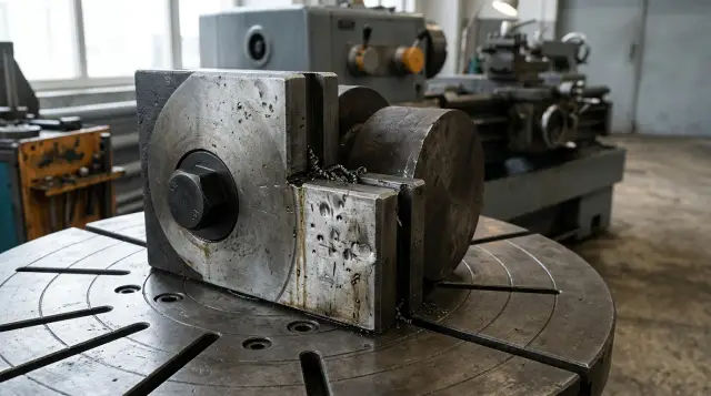
A short, large-diameter workpiece looks ideal for a vertical layout: its weight rests on the faceplate, a crane lowers it from above, and gravity does not try to pull the metal out of the clamp. In practice, this geometry quickly exposes the difference between the catalog machining diameter and a machine that can actually run the process.
Spindle power is rarely the first limit. Chips fill the cavity, the boring tool cannot reach a shoulder, jaws extended outward take travel away from the slide, and a heavy casting seats differently after unclamping. If you check only part diameter and weight, you can choose a machine that is correct on paper and wrong for the job.
Catalog diameter is not working space
Maximum turning diameter answers only one question: what circle can the cutting edge describe in the stated configuration? It does not promise that the jaws, their fasteners, turret body, boring bar, nozzles, and the chips created during cutting will all fit in the same position.
The problem gets worse near the lower outside edge of a short disk. To reach it, the tool and turret move down close to the faceplate. A tall jaw or a raised step on the fixture reaches the same height as the holder body. The contour may fit the X-axis specification, while a collision is already unavoidable on the combined X-Z contour.
Check four diameters separately: the largest raw-workpiece diameter before roughing, the jaw swing, the fastener swing, and the usable diameter at the slide's actual Z position. The last value is often missing from sales tables. You obtain it from the machine envelope model or a layout check made by the supplier.
Do not build only the finished-part contour. Build three states: the raw workpiece with casting allowance, the part in the first setup, and the flipped part in the second setup. Add the jaws in their real positions to each state, not an abstract chuck circle. This immediately shows where a jaw extends past the faceplate, where the turret loses access, and whether a crane can remove the part without taking out a tool.
A few millimeters of clearance on a screen do not make the layout workable. Account for setup error, runout on the unfinished locating surface, a projecting bolt head, jaw travel during release, and a layer of chips on the faceplate. The machine and workholding manufacturers specify safe clearance, so a universal number is more dangerous than an honest model review.
Chips stay where the insert cuts
Gravity helps with loading on a vertical machine, but it does not guarantee chip removal. During outside turning, coils can fall away from the tool and reach the conveyor. When boring a blind cavity, they fall into the part, collect around the bar, and pass under the insert again.
A short, wide workpiece behaves like a bowl. Its bottom blocks the direct route to the chute, a tall rim holds tangled swarf, and coolant spins it with the part. The result is familiar: random scratches across the bottom, a chipped cutting edge, a load spike, a bundle around the bar, and an operator stop for manual cleaning. A conveyor below the work zone cannot fix the problem until the chips leave the cavity.
Okuma descriptions of vertical lathes separately mention an enlarged chip evacuation system and a choice of conveyor direction. This is not a minor sales detail. The manufacturer is distinguishing two jobs: get chips out of the cut, then carry them out of the machine. On a part with a deep pocket, the first job is harder than the second.
First, create breakable chips with the cutting data, insert geometry, and coolant aimed at the cutting point. You cannot cure long stringy swarf by reducing feed "to keep things calm": a feed that is too low often prevents the chipbreaker from forming a short curl. Start with the insert maker's operating window, then confirm it with a test cut in the actual material.
Cut direction matters as well. If the geometry allows it, choose a path that sends the curl toward an open diameter instead of pushing it into a blind corner. For a deep pocket, provide programmed tool exits and controlled flushing. An operator must not pull out a bundle with a hook between automatic passes while the door is open and the machine has not completed a safe stop.
Do not judge this on the clean first part. Run a cycle that produces roughly the series chip volume, using the same allowance and material. If the door must be opened after several pockets, the process already contains a manual operation even if the process sheet omits it.
For this test, weigh or calculate the metal to be removed, mark collection points, and define a stop condition in advance. After every operation, the operator watches through the guarded window and records whether chips remain on the bottom, wrap around the bar, or reach the conveyor. Then inspect the filter, tank, and conveyor joints. This separates a local cavity problem from inadequate capacity in the complete system.
Pay special attention to the final finishing pass. Roughing chips may leave acceptably while a thin finishing ribbon remains in the bore and passes under the insert on the next revolution. The mark appears after the dimension has already been generated. An acceptance test based only on size and average roughness therefore misses an intermittent defect. Inspect the whole circumference, repeat the pass on a warm machine, and check a new insert after a predetermined number of parts.
An air gun inside the enclosed area sometimes helps with dry, breakable chips, but it is not a universal answer. The jet scatters sharp fragments, raises coolant mist, and can drive particles under the locators. Coordinate any automatic air blast with the machine manufacturer, enclosure, and mist collection system. A correctly aimed coolant stream is usually more predictable for wet, heavy swarf.
Boring depth is measured by access, not Z travel
Z travel shows where the slide can move, but deep boring depends on which tool can reach the surface and remain stiff. The bore in a short part may be shallow compared with total machine travel, yet a tall outer rim, narrow opening, or internal shoulder can force the insert far away from the bar support.
People often blur three different dimensions: bore depth, boring-bar overhang from the clamp, and the head's radial reach to the surface. Overhang controls deflection and vibration tendency. Bar diameter is limited by the bore. The front-end shape decides whether the tool can pass behind a shoulder without rubbing on its back side.
The Sandvik Coromant turning handbook recommends minimizing overhang and using the largest possible bar diameter for internal turning. Its guidance table gives approximate limits of 4 bar diameters for a conventional steel bar, 6 for a carbide bar, 10 for a damped steel bar, and 14 for a carbide-reinforced damped bar. These are boundaries for selecting a tool class, not permission to program the maximum cutting data automatically.
Record this ratio for an initial estimate:
L/D = working overhang from the holder support face to the insert tip / boring bar diameter
If the bore accepts an 80 mm bar and the required overhang is 480 mm, L/D equals 6. A conventional steel bar is already a poor starting point for this layout. Shorten the overhang, increase the diameter, change the operation sequence, or use a damped system. Reducing depth of cut without correcting the layout sometimes only moves chatter to another set of cutting data.
The turret adds another limit. A long bar may enter the bore while a neighboring tool, block body, or coolant hose hits the outer rim. Check the whole assembly at approach, cutting, exit, and indexing positions. A simulation that follows only the insert tip leaves the most expensive collisions out of view.
A jaw beyond the faceplate changes the clamping calculation
Moving a jaw outward may be necessary when the workpiece approaches the machine limit, but this is no longer a standard clamp. The jaw's center-of-mass radius grows, more mass rotates on a large circle, and the force acts at a greater height. At the same time, geometric clearance to the guard, slide, and tool shrinks.
The Kitagawa power-chuck manual directly relates the loss of external gripping force to the square of rotational speed. It also says that a larger center-of-mass radius and greater top-jaw mass increase that loss. Another section warns that when the gripping center is higher than it is with the standard soft jaw, loads on the master jaw, T-nut, and bolts rise, so allowable actuator force must be reduced according to the instructions.
That warning breaks the popular idea that "the part is large, so we will just raise the pressure." Hydraulic pressure is not the same as force at the contact, and the maximum static force in a catalog was measured with standard jaws at a specified measuring point. A tall welded jaw or massive special jaw creates another lever arm. Without a calculation from the workholding manufacturer, more pressure can overload the fasteners before it provides the required holding margin.
The Haas operator manual states a conservative rule: chuck jaws must not project beyond the chuck diameter, and the part must not be larger than the chuck. A specific vertical machine and special faceplate may have manufacturer-approved layouts with radial jaw projection. That approval must appear in the machine, chuck, and fixture documentation. You cannot infer it from the fact that the door closes.
Before ordering the machine, ask the supplier for a calculation or allowable chart for the actual jaws. Inputs include each jaw's mass, center-of-mass location, gripping height, rotational speed, gripping direction, pressure or draw force, friction coefficient, and cutting forces. If some data is unknown, the answer should be a limited test speed, not the spindle's catalog maximum.
The most useful chart shows remaining gripping force across the full speed range, not a single "permitted speed." Attach a dimensioned jaw sketch and its mass so that the next jaw rework does not turn the old calculation into fiction. Heavy machining of the jaw changes its center of mass, moves the contact step higher or lower, and alters the jaw's actual mass moment.
Measure static force with a grip-force meter near the working contact point when the chuck manufacturer allows the procedure and the instrument is rated for the workholding size. A stopped-spindle reading does not prove dynamic force, but it reveals contaminated guides, poor lubrication, and a mismatch between pressure and actual grip. The Kitagawa manual specifically notes that its catalog static force was obtained with the company's standard soft jaw, specified grease, and a defined meter position. That is a good example of why a catalog number cannot be transferred to a homemade tall jaw.
Record permitted speed for the exact part and jaw set in the process documentation. Do not remove the limit automatically for a lighter part of the same diameter, because the jaw radius and mass have not changed. Recalculate when changing from external to internal gripping, because centrifugal force affects retention differently and allowable actuator force may also differ.
A heavy part is stable only until cutting starts
Gravity presses the workpiece against its supports, but it neither centers it nor prevents movement in the faceplate plane. Tangential cutting force tries to rotate the disk, radial force moves it off axis, and interrupted cuts through casting skin apply impacts. Jaws and stops must carry these loads without relying on accidental friction against a dirty locating face.
Keep seating and clamping separate. Seating asks whether the locating surface touches every support. Clamping asks whether the forces are sufficient during rotation and cutting. A hydraulic gauge confirms pressure, but by itself it does not confirm seating, jaw-stroke position, or actual force on the part.
A short, heavy casting becomes especially troublesome after the first setup. It may stand on three points on its rough locating face. After flipping, the machined face lands on a chip thinner than the visible gap, the jaws close normally, and an indicator shows axial runout. If the operator taps the part down with a mallet under holding pressure, the action hides the cause and changes stress in the workpiece.
Good workholding provides defined supports, coolant and chip escape routes, and access for cleaning. A repeatable process may use air seating confirmation or separate sensors if the selected system supports them. A sensor does not repair a poor support shape: its channel clogs quickly when the outlet sits in a chip pocket.
Mass also affects transient motion. Spindle acceleration, braking, and an abrupt speed change create torque absent from the static clamping calculation. An acceleration limit may matter more than the maximum speed. Recheck grip and part position after a power loss: the Haas manual separately warns that pressure loss can allow a part to shift in the chuck.
An asymmetric workpiece needs an imbalance calculation and an approved speed. The Kitagawa manual requires reduced speed for significant imbalance and consideration of dynamic gripping force. Do not add a counterweight by eye. It becomes another rotating mass, loads the spindle, and needs fastening calculated for the same speed.
Collision starts before the cutting edge arrives
Most CAM checks monitor the tool tip and holder. On a vertical turning center with a large, short part, the hazardous volume is wider: it includes the turret, neighboring blocks, jaw screws, nozzles, guards, lifting gear, and the jaw position after release.
Make a clearance matrix for every operation instead of one overall screenshot. It must include five states:
- On approach to the outside diameter, confirm clearance from the turret body to the rotating jaws.
- While boring the bottom, check the back of the head against the inner rim and the chip layer.
- On exit after a pass, check the insert and bar against the shoulder with a possible chip bundle included.
- During indexing with the spindle stopped, check every neighboring tool against the part.
- During release and removal, confirm the route for the open jaw, crane, and lifting device.
Every matrix value needs a source: the machine model, a workholding drawing, a tool measurement, or the clearance assigned by the process engineer. "It clears in the model" means nothing when the model shows a closed jaw but the real jaw travels outward during release.
Confirm the safe path with the spindle stopped and in the setup mode provided by the manufacturer. Install a dummy or checking assembly in place of the cutting tool first, then move through critical points at limited feed with the stop control ready. Bypassing interlocks for a better view is unacceptable. The guard is there to protect against the rotating components and flying chips involved in this exact process.
Remember the part of the tool behind its mounting point. A long boring bar or modular adapter can hit a cover during a station change even though its working end is far from the part. A long tool may require a dedicated position, an indexing restriction in part of the envelope, or manual change under the manufacturer's procedure.
Cutting data must help evacuation
Treating an unstable process by reducing speed and feed together usually makes at least one problem worse. Lower speed reduces centrifugal grip loss in an external clamp and may settle an imbalance. Feed that is too low, in contrast, can produce a continuous chip, rubbing instead of cutting, and unreliable chipbreaker action.
Choose cutting data around two independent constraints. First, set a safe spindle speed from clamping, imbalance, workholding mass, and spindle limits. Then, inside that range, select cutting speed, feed, and depth for the material, insert, rigidity, and required chip form. If the ranges do not overlap, changing the insert or process makes more sense than a compromise that both clamps and cuts poorly.
Constant surface speed raises spindle rpm quickly as the tool moves toward center on a large diameter. Set a maximum-speed limit before the constant-speed command, using the value from the clamping calculation. Exact syntax depends on the CNC, so never copy another machine's G-code without checking the manual. The process sheet should store approved speed as a setup parameter, not as an oral note from the setup operator.
Coolant must reach the cutting edge during deep boring, rather than merely flooding the bore entrance. Sandvik Coromant links accurately aimed coolant on long overhangs to heat removal and shorter chips. Keep pressure and flow inside the limits of the tool, seals, and machine. A narrow nozzle with a high gauge reading can still provide too little flow to carry out the chip volume.
Load monitoring is useful as a process-change signal, but a threshold cannot replace inspection of chip form. A bundle can scratch the finished surface before power rises noticeably. During prove-out, record chip appearance, collection location, insert condition, load, and the time until cleaning becomes necessary.
Machine acceptance starts with your workpiece
A small-diameter demonstration part proves nothing for a short, heavy disk. The acceptance test must reproduce the worst geometry, mass, material, allowance, cavity depth, jaws, and tools in the future process. If the actual blank is expensive, make a process mock-up with the same hazardous contours and a similar moment of inertia, agreed with the machine manufacturer.
Before the run, write measurable acceptance criteria:
- Jaws remain inside their approved stroke, and calculated speed does not exceed the workholding limit.
- Every critical X-Z position maintains the assigned clearance, including indexing and open jaws.
- Boring holds size and finish at the required overhang without a forced cutting-data reduction below planned output.
- Chips leave the cavity and reach the conveyor without manual intervention for the agreed series of cycles.
- After removal and reloading, the part seats on the locators and position and grip checks give an unambiguous result.
"The machine cut one part" is too weak a criterion. Test repeatability after warm-up, normal conveyor loading, an insert change, a stop, and a restart. Check access for cleaning filters and the tank. High chip volume quickly turns awkward maintenance into lost shift time.
Run a separate acceptance operation for loading and removal. Check the lifting device, hook position, door opening, open jaws, and where the operator guides the part. The workpiece must not hang on one jaw or require a person to hold it by hand over the faceplate. Also try removing the finished part while it is warm and wet with coolant, because a dry, clean mock-up behaves more conveniently than the real component.
The center of gravity of the lifting device and part must stay below the suspension point in the approved orientation. If the first setup changes mass distribution, the sling arrangement may also need to change. Lifting-eye locations, thread, and rated load belong in the process just as the cutting tool does. For series work, a dedicated device that avoids finished surfaces and keeps hands out of the gap between part and jaw is sensible.
Ask to retain the actual test files: CNC program, tool table, jaw positions, pressure, speed limit, and photos of the chips after a cycle. This is not paperwork for its own sake. Without these records, a successful demonstration does not become a reproducible setup in your plant.
When selecting a machine with EAST CNC, give the specialist more than the finished-part drawing. Send the raw-workpiece model, weight, material, allowances, locating plan, and required cycle time. Consultation and commissioning can then work from the actual layout instead of a match between two catalog rows.
Sometimes a horizontal layout is the honest choice
A vertical center remains a strong choice for a heavy disk when the workholding fits the envelope, chips leave the cavities, and stiff tooling can reach the deep surfaces. Gravity simplifies loading and seating on the locators. It does not cancel the clamping, clearance, and dynamic calculations.
Compare a horizontal turning center when a through bore lets chips leave freely, long internal work needs straightforward axial access, or a chuck and tailstock can safely support the workpiece. For a very large, short part, horizontal loading and retention may instead become the main risks. Choose orientation from the whole operation, not from one convenient property.
Sometimes the right answer is a larger vertical machine. That makes sense when the extra diameter truly gives the turret and jaws more room. Buying reserve capacity based only on maximum diameter is pointless: turret geometry and the lower Z-travel boundary can remain similar on the larger model.
Compare models with the same assembly. The supplier places the same blank, jaws, tool blocks, and lifting device in both digital machine models, and the process engineer checks the critical coordinates. Otherwise, the larger model can win on the "maximum diameter" row without adding anything near the lower face. At the same time, compare torque at the required speed, permitted table load, moment of inertia, jaw travel, loading height, and the ability to place the required boring bar in the standard magazine. Part mass and allowable load are not synonyms either: the latter may include the chuck, adapter plate, and jaws. Confirm this in the manual for the exact machine.
In another case, change the process: machine the deep cavity before fitting a tall external jaw, separate roughing and finishing clamps, add a special low faceplate, or move one boring operation to another machine. The cost of a second setup can be lower than permanent trouble with chips and chatter.
Decide from four proven items: a complete collision model, a dynamic clamping calculation, a boring test at the required L/D, and a cycle that removes the real chip volume. If a supplier can confirm only weight and diameter, the process is not confirmed. On a short, large-diameter workpiece, the hidden centimeters around the jaw and inside the cavity decide whether the machine becomes production equipment or an expensive place for manual cleaning.
FAQ
Is a vertical turning center suitable for a short large-diameter part?
Yes, if the work envelope holds the part, jaws, turret, and tool in every position. A vertical layout makes loading a heavy disk easier, but chips in blind cavities and access to lower surfaces need separate proof.
Why can I not use maximum turning diameter as blank diameter?
The catalog value describes a reachable cutting circle in a stated configuration. Casting allowance, projecting jaws, fasteners, and the turret body reduce the diameter that is actually usable.
Can jaws extend past the faceplate edge?
Only when the machine, chuck, and workholding manufacturers approve the exact layout and its limits. Outward projection changes centrifugal grip loss, bolt load, and safe speed, so geometric clearance alone is not enough.
How do I remove chips from a deep cavity on a vertical machine?
Create short controlled chips, aim coolant at the cutting point, and give them a route toward an open diameter. The conveyor only helps after the chips have left the part.
How can I tell whether a boring bar is too long?
Calculate working overhang L divided by bar diameter D and compare it with the tool maker's guidance. Also check the complete assembly behind shoulders, because an acceptable L/D does not guarantee access.
Will reducing feed stop chips from collecting?
Not necessarily. Feed below the chipbreaker's operating window often makes a long ribbon, so correct chip form with insert geometry, speed, depth, and coolant delivery as well.
Does gravity hold a heavy workpiece on the faceplate?
It presses the part against its supports but does not center it or resist tangential cutting force. Jaws and stops still need calculations for sliding, rotation, acceleration, and braking.
What data is needed to calculate a special jaw?
You need jaw mass and center of mass, gripping height, speed, gripping direction, actuator force, cutting forces, and contact properties. Check the calculation against the chuck and machine manuals, and measure dynamic force when required.
What should a vertical-center acceptance test check?
The test should reproduce hazardous contours, mass, tool overhang, workholding, and chip volume. Check collisions, seating, dynamic grip, boring quality, and operation without unplanned manual cleaning.
When is a horizontal machine better for a disk-shaped part?
It may be better with a through cavity, a direct axial chip exit, and a workpiece that can be supported safely. Compare the complete route because horizontal loading of a heavy disk creates its own limits.