
A vertical turning center is better for a 1.2-meter disc
A vertical turning center usually holds a 1.2 m disc better, but weight, loading, chips, floor space, and the foundation decide.
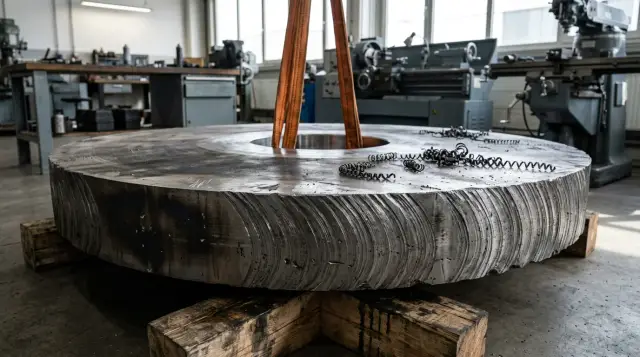
A 1.2-meter-diameter disc is almost always better machined on a vertical turning center. The workpiece rests on the faceplate under its own weight, the crane lowers it from above, and the operator does not have to hold a heavy part against the vertical plane of a chuck. But 'almost' matters more than a sales promise: a long hub, a deep bore, automated loading for a production run, or proven horizontal tooling can change the answer.
Diameter alone does not select a machine. Before requesting a quote, you need the weight, height, center of gravity, material, stock allowance, tolerances, annual volume, and process route. If you send a supplier only the words '1,200 mm disc,' you can receive a machine whose nominal diameter fits while its door, spindle torque, faceplate load limit, or tool travel does not fit the actual part.
A 1,200 mm diameter needs clearance, not a catalog match
A machine with a maximum turning diameter of exactly 1,200 mm is not automatically suitable for a 1,200 mm disc. The catalog limit describes the machining envelope for a stated configuration, but it does not promise a convenient setup, chuck-jaw clearance, safe tool approach, or room for chips. The working area must contain the raw forging or casting, jaws, clamps, tool block, and tool-change path as well as the finished contour.
The official catalog for the Okuma VTM-1200YB is a useful example of a boundary: the maximum machining diameter is 1,200 mm, chuck diameter is 1,250 mm, and the stated workpiece load is 3,000 kg, or 5,000 kg together with the chuck in a separate configuration. That does not grant blanket permission to turn every disc of this diameter. A part at the limit leaves little freedom for a rough rim, casting eccentricity, and an external tool.
The ram-type DN Solutions PUMA VTR range starts with a model rated for a 1,250 mm maximum diameter, while the next size group accepts 1,600 mm. The difference between 1,250 and 1,600 mm looks like expensive empty space until the process engineer adds the protruding jaw and toolholder to the workpiece diameter. Buying the next size 'just in case' is also wrong: machine mass, height, foundation cost, and noncutting travel all rise. Request a collision-check drawing from the manufacturer for the selected turret or ram.
I normally ask to see three positions on one drawing: loading the raw workpiece, outside turning at the maximum radius, and boring at full depth. If any one of them works only with a special holder, that fact belongs in the specification before the contract, not as a discovery during commissioning.
A disc seats itself on supports on a vertical axis
Gravity provides the main advantage of a vertical layout for a short, heavy part. A crane lowers the disc onto the faceplate, the workpiece rests on adjusted support points, and the jaws mainly center it and create the force needed to resist cutting. On a horizontal spindle, the crane holds the disc at the chuck while the setter lines it up with the supports and tightens the clamp. Any gap turns the part's weight into an overturning moment around the jaws.
People often blur this distinction with the word 'rigidity.' Machine rigidity and workpiece stability are different things. A cast bed can be very rigid while a poorly designed setup still lets a thin disc bend or shift. A vertical arrangement does not repair weak workholding; it puts the steady load in a more favorable direction.
You can quickly estimate the likely weight of a solid steel disc before receiving data from the foundry:
m = π × (D² - d²) / 4 × h × ρ
D = 1.20 м, d = 0.20 м, h = 0.12 м, ρ = 7850 кг/м³
m ≈ 1302 кг
This is a cylindrical-ring calculation without pockets or steps. It does not replace the mass from a 3D model, but it immediately rules out an offer with a 1,000 kg load limit. When checking the spindle assembly, add the mass of the jaws, adapter plate, and fasteners if the manual counts them as part of the load. Ask the manufacturer for a chart of permissible mass against spindle speed and center-of-gravity position, not a single number.
A thin disc requires a different kind of care. Its own weight helps seat it on the supports, but excessive jaw force turns the circle into a polygon. The dimension moves after unclamping even though the in-machine indicator showed a good result. The number of supports, equal support height, tightening sequence, and inspection after removal all matter. A vertical machine makes the job easier but does not remove the need to calculate deformation.
A horizontal layout wins when the disc has a long hub
A horizontal center becomes a strong candidate when the 'disc' is really a short shaft with a large flange. A long hub, machining from both sides, a deep axial bore, or the option to support the part with a tailstock changes the load path. The workpiece can be located on a cylindrical section, supported by a center or steady rest, and reached by a boring tool along the machine's natural axis.
Do not compare layouts by outside diameter alone. Calculate the ratio of axial length to diameter and mark the center of gravity after each setup. A flat ring 180 mm high and a 1,200 mm part with a 900 mm hub need different answers, even if both are called discs on the order.
A horizontal machine can also make sense in an established shop. If the plant already has a proven faceplate, angled jaws, steady rest, loading trolley, and programs for the part family, moving to a vertical center requires new tooling and another round of process approval. Yet 'we have always turned it horizontally' is not a calculation. Compare the old route by rigging time, setup count, drop risk, access for measurement, and dimensional stability.
For a disc without a long hub, the horizontal layout usually loses at the workholding stage. A loading cradle, lift table, or dedicated trolley holds the heavy part until the clamp is tight. That equipment occupies the area in front of the machine and becomes part of the cycle. If a supplier shows cutting time alone, the productivity estimate omits the most awkward operation.
Loading determines both safety and cycle time
For one-off and small-batch discs, vertical loading with an overhead crane is usually simpler. The rigger sees the seating supports, lowers the workpiece along the faceplate axis, and removes the slings after a preliminary clamp. On a horizontal center, the door and guarding restrict sling angles, while the operator must control clearances between the part face, jaws, and turret housing.
Safety cannot be reduced to 'the crane can lift the weight.' Check the whole route: shipping container, rigging location, hook height above the open machine, spreader clearance through the door, control position, and the area where a person removes the sling. A vertical center can be tall, and an existing crane may have enough capacity but too little lifting height. The choices then are a pit, a different spreader, or a revised layout.
Record the loading cycle on video or model it to scale. The sequence must contain the real actions:
- Clean the supports and confirm that the jaws are opened to the recorded position.
- Lift the workpiece with an inspected spreader, move it without passing over people, and bring it into the work area.
- Seat the part on every support, apply the preliminary clamp, and only then slacken the slings.
- Check runout and seating, tighten it in the specified sequence, and remove the lifting attachment.
- Close the guarding and permit the start only after clamp confirmation.
This sequence exposes questions absent from the catalog: where the spreader will rest, whether the operator can reach a jaw, whether the probe interferes with slings, and where chips remain before the next loading. Automation may deserve study for a production run, but a large disc rarely justifies a robot on fashion alone. A gantry loader, pallet, or rotary table must pay for itself through shorter cycle time and lower risk, not through a handsome presentation cell.
Floor space includes maintenance and crane movement
A vertical center is often shorter than a horizontal machine rated for the same outside diameter because it does not have a long spindle, chuck, part, and tailstock line. It is taller and can be wider around the column, while access remains necessary for the conveyor, coolant tank, hydraulic unit, cabinet, and component removal. The claim that it takes less floor space is true only after maintenance areas are drawn onto the shop plan.
The Okuma VTM-1200YB catalog gives a required area of roughly 5.5 by 4.3 m in the base configuration and a height of about 5.5 m. Machine weight is about 28 metric tons. These figures are useful not as a recommendation for that model, but as a scale check: equipment that genuinely handles a 1,200 mm diameter will not fit in the corner vacated by a small manual lathe.
Make a floor plan and a separate vertical section. On the plan, show open doors, the pulled-out chip conveyor, coolant-tank removal, crane position during loading, and a temporary workpiece location. On the section, mark the hook's lowest point, spreader height, sling length, top of the part, and roof obstructions. Only then can you compare square meters.
A horizontal center has a longer frontage, but its loading height is often lower. That can settle the choice in an older shop with a low crane runway. A vertical center can make the production flow around short discs more compact, but a tall machine may require moving lights, ducts, or cable routes. Such work is rarely included in the machine price and can easily delay startup.
Chips fall downward, but sometimes onto the workpiece
A vertical layout does not guarantee perfect chip removal. During outside turning, chips and coolant generally go down toward the chute, which helps. When boring a cup-shaped part, chips can collect in the pocket, re-enter the cut, damage the surface, or block a measurement probe from reaching its datum.
Manufacturers design channels and flushing to address this. The Okuma VT1000EX brochure specifically names an enlarged chip-drop opening, a stainless-steel chute, and high-flow flushing. The V920EX description also mentions smooth chip flow and a conveyor that can discharge to the rear or side. I agree with the direction of that design, but the marketing sentence does not answer the question about your chips: coiled steel ribbon, short cast-iron fragments, and gummy aluminum chips behave differently.
Request a cutting trial with the actual material, stock allowance, and a similar pocket shape. Do not judge only by the cleanliness of the finished part. See whether chips wrap around jaws, block the screen, carry coolant out on the conveyor, prevent support cleaning without reaching inside, and add minutes to cleaning between parts.
On a horizontal center, chips usually leave the part more easily, especially during deep boring with an open lower sector. But a large vertical face can shield coolant flow, and long chips can still wrap around the chuck. Chipbreaker geometry, feed, and depth of cut often matter more than spindle orientation. Treat the claim that a vertical machine clears chips better as a hypothesis until a trial proves it.
The machine manual and the ground determine the foundation
You cannot declare in advance that a vertical center always needs a heavier foundation. A large vertical machine does concentrate tens of tons on a relatively short base and has a high center of mass. A horizontal machine spreads weight over a long bed but can react more strongly to differential settlement between supports. Both require calculations based on the installation drawing for the selected model.
Start with the allowable load on the existing slab and information about the soil beneath it. Then obtain the ordered machine mass, support coordinates, point reactions, concrete thickness and strength requirements, anchoring, isolation-joint details, and leveling tolerances from the manufacturer. A universal thickness copied from someone else's manual is dangerous. Even manuals from one manufacturer prescribe different arrangements for different series and versions.
The foundation works with the machine. If one support settles, geometry changes, guideways twist, and the measured size begins to depend on axis position. An installation crew can level the machine again, but continued settlement will bring the fault back. In areas with frost, high groundwater, or nearby presses, a structural designer must check the base and vibration instead of merely adding concrete thickness.
Include a geometry acceptance check after installation and a repeat check after an agreed operating period in the technical specification. Record the instrument, measurement points, permitted deviations, and responsibility for correction. On a heavy machine, this costs less than arguing later about a taper that appeared after several months.
The part matrix decides, not the machine label
For a flat 1,200 mm disc, the starting choice is a vertical turning center with a working diameter larger than the blank, enough faceplate capacity, and confirmed overhead crane access. A horizontal center must win on a specific condition, such as a long hub, tailstock work, an existing automated line, or a building-height limit.
Put this logic in a table before speaking with vendors:
<table> <thead> <tr> <th>Condition</th> <th>Vertical center</th> <th>Horizontal center</th> </tr> </thead> <tbody> <tr> <td>Short, heavy disc</td> <td>Preferred: weight seats it on supports</td> <td>Needs support during loading and clamping</td> </tr> <tr> <td>Long hub</td> <td>Check height, Z travel, and tool access</td> <td>Often easier to locate and support along the axis</td> </tr> <tr> <td>Crane loads from above</td> <td>Direct path if hook height is sufficient</td> <td>Requires access through the front door</td> </tr> <tr> <td>Low building</td> <td>Machine and sling height may rule it out</td> <td>Often easier to fit vertically</td> </tr> <tr> <td>Deep enclosed pocket</td> <td>Requires proven pocket flushing</td> <td>Chips can fall through the open lower sector</td> </tr> <tr> <td>Limited line frontage</td> <td>Short layout is often easier</td> <td>Long bed needs more frontage</td> </tr> </tbody> </table>After the first selection, send the same package to two suppliers: part and blank drawings, 3D model, mass and center of gravity, material and hardness, stock allowances, runout and flatness requirements, production volume, desired cycle, available crane, and building plan. Ask for a process route, workholding scheme, spindle-speed calculation, layout drawing, and list of items excluded from supply.
Read the maximum-speed line for the installed mass with particular care. With a large disc, it is dangerous to take cutting speed from a handbook and immediately convert it to revolutions. Material and insert are not the only limits; imbalance, jaws, moment of inertia, and the spindle's manual chart also govern it. A cutting trial must include rough-part imbalance, not just an already balanced demonstration part.
Motor power does not replace low-speed torque
For a 1,200 mm disc, compare spindle torque in the working range rather than engine power on the brochure cover. At the outside radius, even a moderate cutting speed produces low revolutions. At 180 m/min and a 1.2 m diameter, for example, the calculation gives about 48 rpm. If the gearbox, motor, and control deliver full torque above this range, the advertised kilowatts will not become the required force at the cutting edge.
Start the calculation with the operation that demands the most torque, often rough turning through the casting skin on the outer band. Estimate cutting force from the material, depth, feed, and insert geometry, then multiply its tangential component by the machining radius. Add a sensible allowance for uneven stock. The supplier should show the power and torque chart, select the gearbox range, and state the permissible duty. A single 'maximum torque' value without speed and duty is insufficient.
Moment of inertia answers a different question: whether the drive can accelerate and stop the workpiece in an acceptable time. Two discs of equal mass behave differently if one carries its metal at the outer rim and the other nearer the center. Mass therefore cannot replace the moment of inertia from a 3D model. Acceleration may need limits both to protect the drive and to keep the part from slipping in the jaws.
Raw-workpiece imbalance adds another limit. The center of gravity of a casting may miss the datum axis because of gates, bosses, and uneven allowance. Centrifugal force rises with the square of angular speed, so doubling revolutions makes the imbalance force four times larger. Do not run the rough setup at a speed calculated for an already trued part. The process engineer sets a reduced range for the first pass and raises speed only after checking runout and removing heavy spots.
The chuck's rated speed does not authorize every jaw set at the same limit. Tall top jaws increase radius and fastener load, while centrifugal force reduces available clamping force. For a special faceplate, the tooling designer must check bolts, T-slots, supports, and the permissible speed of the whole assembly. The spindle plate applies to the standard configuration unless the manual explicitly says otherwise.
Drive selection affects productivity, but chasing seconds often damages this process. For a large disc, crane time, datum cleaning, alignment, and inspection can exceed acceleration time. More power for a faster start makes little sense if an operator then spends ten minutes digging chips from a pocket. Build the actual cycle balance first and decide where a costlier option truly shortens it.
The tool system must match reach and force. At a large radius, a weak holder shows up as chatter, bands on the face, and rapid edge failure while the spindle remains far below its limit. Check holder section, boring-bar overhang, ram position, and distance from tool support to the cutting point. A ram-type vertical machine generally gives a more direct force path for heavy cuts, while a turret center changes tools faster. The route decides, not the layout name.
The request for a cutting trial must specify both conditions and output. Record material and skin condition, allowance range, tool, feed, depth, revolutions, spindle load, vibration level under the agreed method, edge life, and actual time. After roughing, measure workpiece movement against witness marks. This makes the supplier confirm the combined drive, clamp, tool, and cutting data rather than one power figure.
Check stopping under power loss and a normal stop separately. A large rotating mass should not make door release an indefinite wait, but braking too hard loads the clamp. Documentation should state stop time for the agreed inertia, door-interlock logic, and a safe way to remove the part after a drive fault. These details belong to the ordered configuration, so a verbal sales answer is not enough.
Test the thermal state on the actual cycle as well. A large disc often runs for a long time and is then measured on the machine. Heat from cutting, bearings, and coolant changes the temperature of the part and machine; a 1,200 mm diameter makes even a small gradient visible in the tolerance. Agree on measurement temperature, stabilization time, sensor position, and compensation rule. If final inspection occurs after cooling in the shop, acceptance must repeat that condition.
A finish requirement cannot be separated from metal removal. A machine that confidently cuts through skin with a wide tool may fail to hold flatness on a thin ring after the jaws release. Sometimes the better route is roughing, natural or specified stress relief, another setup, and a finish pass with lower clamping force. The second setup adds time but avoids trying to compensate for internal stress with a program offset.
Acceptance must repeat the difficult part of the process
The buyer should accept the ability to make the agreed part, not abstract machine accuracy. Laser checks of the axes and the maker's test piece matter, but they do not prove the stability of a 1,200 mm disc in your tooling. The acceptance program should include loading, alignment, rough removal of uneven stock, a finishing pass, measurement while clamped, and measurement again after release.
A bad scenario is easy to recognize. The supplier brings a balanced ring, the setter clamps it in soft jaws, takes a light pass, and produces an attractive report. Production then receives a casting with a heavy boss, the crane cannot seat it without tilting, chips fill the inner bowl, and flatness changes after unclamping. The machine is technically sound, but the process was never proven.
EAST CNC selects, supplies, and commissions CNC turning machines, so it is better to send the part data before choosing a model. State the full required scope in the request, including tooling, commissioning, and service when the plant needs those items.
For an ordinary flat disc, the final answer remains vertical. Choose against it only when the part drawing, crane, building, or existing process gives the horizontal axis a measurable advantage. If a supplier will not show workholding and the loading path on your drawing, they have offered a machine size, not a working process.
FAQ
How much diameter clearance does a 1,200 mm disc need?
There is no universal percentage. The working area must contain the raw contour, jaws, holder, and safe tool path, so request a collision check using your 3D model.
Can a 1,200 mm disc run on a machine rated for exactly 1,200 mm?
It may be formally possible, but it is a boundary choice in practice. Allowance, casting ovality, or protruding jaws can push the actual envelope beyond the work area.
Why does a vertical center hold a heavy disc more steadily?
The disc rests on supports and gravity acts toward the faceplate. The jaws do not constantly resist an overturning moment as they do on a horizontal axis.
When is a horizontal turning center better than a vertical one?
It is often better for a part with a long hub, deep axial bore, or support from a tailstock and steady rest. Limited building height and an established loading line can also decide in its favor.
How do I estimate blank weight before choosing a machine?
For an early estimate, split the model into cylinders and rings, calculate their volume, and multiply by material density. For final verification, use mass and center of gravity from the 3D model and add tooling according to the machine maker's rules.
Does a vertical turning center need a special foundation?
The installation drawing for the exact model and a calculation of the existing base decide. Mass, support locations, soil, nearby equipment, and anchoring requirements matter more than the general label 'vertical.'
How can I tell whether the overhead crane is sufficient?
Check capacity and geometry over the entire route. Hook height must accommodate the machine, workpiece, spreader, and slings, and the load must pass through the open guarding without a dangerous tilt.
Which machine removes chips from a large disc better?
For outside turning, a vertical arrangement usually drops chips downward well. Chips can collect in a deep bowl, so prove the result with the actual material, cutting data, and flushing system.
What information should I send a machine supplier?
Send part and blank drawings, a 3D model, weight, center of gravity, material, allowances, tolerances, volume, cycle target, crane data, and a building plan. Without them, the supplier selects a catalog diameter rather than a process.
What belongs in the machine acceptance test?
Repeat the hardest part of the real route: loading, clamping, rough imbalance, chip removal, and the finish dimension. Measure before and after unclamping, or workholding distortion can easily look like machine accuracy.