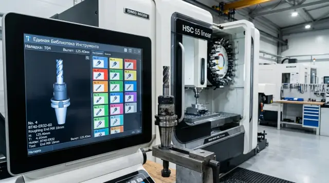
Unified Tool Library to Keep CAM and the Shop Floor in Sync
A unified tool library helps keep tool lengths, holders and offsets consistent between CAM and the shop floor so the program matches the machine.
Why the CAM program and the machine diverge
Most often the reason is simple: CAM sees one tool assembly, while a different assembly is mounted on the machine. On the screen the trajectory looks clean and nothing appears to hit the chuck or the part — the check passes. But on the first run the cutter reaches closer than expected or hits a place that was empty in the simulation.
Usually the error starts long before the run. A programmer once saved a working assembly, and CAM keeps inserting that old overhang from a previous job. Days or weeks later the shop installs a different holder because the original wasn’t at hand. The geometry has changed, but the tool name stays almost the same. To the eye everything looks similar. In fact it’s a different assembly.
On CNC lathes such a difference quickly becomes noticeable. Even an extra 10–15 mm of overhang changes stiffness, safe approaches and collision risk. If the program assumes a short tool but a longer assembly is in the turret, the simulation can lull you into a false sense of security.
There is a second common cause: offsets drift away from the program. An operator adjusts an offset to hit size faster. For that part it works. Later the same program runs on another blank or after a tool change, and the previous tweak interferes. CAM calculates from one dataset, while the machine cuts with numbers that have shifted.
The tool magazine adds to the confusion. There is almost always a “nearly the same” tool: the same insert, a similar diameter, a nearby slot number. But the holder is different, the overhang is different, and sometimes the setup is different. Visually the difference is small. For the tool path it can be decisive.
That’s why the unpleasant effect appears: the program passes checks but the first real run brings surprises. They usually look like this:
- the approach to the part seems fine, but during cutting the tool is in the wrong place;
- the simulation shows a safe retract, but on the machine the holder comes too close to the jaws;
- the size shifts after the first part even though the code wasn’t changed.
The worst part is that each individual change seems reasonable. The programmer reused an old assembly to save time. The setup technician installed a readily available holder to avoid downtime. The operator adjusted an offset to save the part. Separately these choices make sense. Together they break the match between CAM and the machine.
That’s exactly why a tool library is needed. It won’t eliminate every mistake, but it closes the main source of divergence: different people stop working with different versions of the same tool.
What to store in a tool card
If the database only says “12 mm cutter”, it’s almost useless. CAM and the shop need the actual assembly that sits in the magazine and is used by the program without guessing.
First, separate the tool identifier from the magazine slot. They are different things. Tool T12 might be in slot 7 today and move to 11 after a changeover. If you mix those fields, the mismatch between program and machine appears quickly.
Next comes the assembly itself. The card should state the type and size clearly: turning insert, drill, boring arbor, end mill, diameter, shank size, insert radius. The entry must be understandable at a glance. The person at the machine shouldn’t spend half a minute decoding it.
Specify the exact model of the holder or arbor separately. The same cutting part behaves differently in different holders. Overhang, access to the part and collision risk change. On turning operations this is especially visible: the insert may be the same but the holder is different, and the trajectory no longer matches what CAM showed.
Geometry you can’t guess
Most errors are linked to overhang. The card needs the real overhang from a common baseline, not a value “about the same as last time”. This baseline must be used for measuring, for CAM and for the machine. If a boring arbor extends 93 mm instead of 85 mm, that’s not a small detail. For a narrow groove or internal boring the difference can decide the outcome of the run.
Keep length, radius and offset numbers next to the geometry. Not in a notebook, not in the fitter’s memory, not on an old printout. When the card is linked to the offset, CAM uses the same logic as the machine. If a tool goes for regrind, you change not only the status but also the actual dimensions.
A minimum working card usually includes:
- tool identifier and current slot;
- tool type and its size;
- holder or arbor model;
- actual overhang from the common baseline;
- offset number, its values and current status.
Status is not for reporting only. It lets you start a job without surprises. Simple notes like “in use”, “after regrind”, “replaced” or “needs check” usually suffice. Without status the database quickly becomes an archive of old records where the screen shows one thing and the spindle has another.
How to name tools without confusion
Confusion often starts not in CAM but in naming. If the program uses one name, the setup card a second, and the machine magazine a third, the operator wastes time cross-checking and can still pick the wrong assembly.
You need a single naming template for everyone: programmer, setup tech and operator. A good name shouldn’t be long, but it should answer a simple question: what is this tool and in which assembly is it used?
The easiest approach is to split the name into two parts. The first describes the cutting part: insert type, drill diameter, tap thread size. This part changes rarely. The second describes the assembly: holder, adapter, chuck and the actual overhang. If you move the same insert to another holder or change the overhang, keep the cutting code and give the assembly a new code.
This prevents a common error: the holder was changed but the name remained old. CAM still assumes the old assembly while the machine has different overhang and access limits.
A good template usually includes the cutting tool code, the assembly code, the actual overhang and a version. If a comment is needed, keep it short and clear. For example: “TL-DCMT11 / ASM-BMT55-L82 / v3”. This shows the cutting part is the same, while the assembly and overhang are specific.
Version and reason for change
A version is needed even for small edits. If you replaced a holder, added 8 mm of overhang, moved the tool to another standard assembly — create a new version and don’t overwrite the old one.
A short note about the reason for the change is even more useful. For example: “v3 - new holder, overhang 82 mm instead of 74 mm”. Such a line often saves more time than a long instruction. If the first part showed vibration or lacked clearance, the team immediately sees what changed.
Without a reason the database quickly becomes a set of similar names. After a month no one remembers why “v2_new” or “final_3” appeared. Ban such names from the start.
One simple rule: give one person the final right to record entries. Usually that’s a process engineer or setup technician who maintains the library and verifies new entries before adding them. Others can suggest changes, but one person should decide how an entry is named and where it lives. Otherwise duplicates almost always appear.
How to build the library step by step
It’s better to start not with the entire catalogue but with what is already stable in the shop. Take only the assemblies that operators actually mount: the tool, holder, arbor, insert, and any extension when needed. This way the library quickly becomes usable, not a storage of random entries.
On the turning shop floor this is clear right away. The same insert can be called the same name but be mounted in different holders and give different overhangs. For CAM those are different assemblies even if the insert itself didn’t change.
Measure each assembly as it is mounted in the magazine. Not from a catalogue and not “about the usual”. You need real overhangs, lengths, diameters, fit, holder type and offset number. If the assembly has several parts, measure it as a whole. A couple of millimetres error on the screen can easily become an unnecessary risk at the machine.
Work in small batches, for example 10–15 assemblies. It’s easier to keep order and catch odd mismatches.
After measuring, enter data into CAM immediately without rounding. The fewer intermediate tables, notebooks and verbal notes, the smaller the chance of error. Give each card a single clear name, exact dimensions and a note about which machine the assembly has been verified on.
Then open the machine and compare the library to what’s in the magazine. Slot number, overhang and offset should match. If any item doesn’t match, CAM and the shop will again drift apart.
Once the first working records are collected, clean the database. Remove duplicates, old versions and vague entries like “new drill” or “cutter 2”. Such records usually hinder more than help.
Finally, set a clear update routine. Fix four things: who creates a new entry, who measures the assembly, who verifies it on the machine and who updates data after a holder change or offset tweak. If the database is “everyone a little”, the order quickly disappears. A simple rule works better: changed assembly on the shop floor — update the record the same day.
Example on a simple turning part
Take a common steel bushing with an external diameter, an axial hole and an internal bore. On such a part you immediately see why a tool library is needed. If the programmer uses one tool in CAM while the shop mounts a similar but different one, the first part can be out of size or create extra collision risk.
This job needs only three positions: a turning insert for the OD, a drill for the pilot hole and a boring tool for the final ID.
The programmer doesn’t assemble them by memory or sketch approximate holders. He opens the database and selects only the assemblies actually present on the shop floor: with the specific holder, insert, overhang and offset number. That is the main benefit. CAM calculates the path not for an “approximate” tool but for what the setup tech will mount.
Imagine a simple set. For OD turning the database has T0101 with a turning insert and a 32 mm overhang. For drilling — T0303, a 14 mm drill in a chuck with 78 mm overhang. For boring — T0505, a holder with 95 mm overhang. The program uses exactly those assemblies. So approaches, safe planes and cut depths are calculated from real geometry, not assumptions.
The setup tech receives the setup card and does not hunt for tools. He takes T0101, T0303 and T0505, mounts them in the magazine and uses the same numbers. This saves time and greatly reduces the chance of small swaps that later break program logic.
It’s easier for the operator too. The setup card shows the same identifiers as the machine screen. If the program calls T0505, there is no guessing which boring tool the programmer meant.
The benefit is visible from the first part. The drill doesn’t go deeper because of a different overhang. The boring tool doesn’t approach the jaws closer than CAM expected. The turning tool doesn’t change the contact point just because someone used a different holder.
On simple parts these mismatches seem small. But they eat 10–20 minutes a day in searching, adjusting and re-running. When the library and the shop use the same assemblies, even a short job runs noticeably smoother.
Where mistakes most often happen
Most problems come not from complex geometry but from small mismatches between CAM, the library and what’s actually in the machine. The error usually looks harmless: the program is calculated correctly, but the magazine contains a different assembly. Then unnecessary approaches, wrong lengths, holder marks or downtime follow.
The most frequent failure appears after copying an old card. The programmer takes a familiar record, changes only the insert or diameter, and leaves the holder as it was. In CAM the assembly still looks plausible, but on the machine it’s different. For CNC lathes this is especially bad: even a small difference in holder or overhang quickly changes safe approaches.
Using a calculated overhang instead of a measured one causes many problems. It’s easy to put a neat number like 80 mm on the screen because it was used before or appears in a catalogue. But assembled overhang is almost always slightly different. Those millimetres often break the match between simulation and real machining, especially near the chuck, jaws or fixtures.
Another common mistake is one card for several different assemblies. That seems convenient until the first failure. If the tool is in a short holder today and a long holder tomorrow, those are two different records even if the cutting part is the same.
The database can age quietly. A tool is reground and the length in the card isn’t updated. The setup tech changes an offset to speed the start. A similar holder replaces the original because the needed one is busy. The old assembly is returned to the magazine under the same name. Each story looks small. Together they quickly destroy trust in the library.
In practice it goes like this: a program arrives at the shop, the operator sees a slight size drift and adjusts an offset on the machine. The part runs and the shift is happy, but the library remains outdated. A week later someone else uses the same tool, builds the path from the database and gets geometry that doesn’t match what’s in the magazine.
If you already have a library, monitor not only names. Track who and when changed the overhang, holder, offset and status after regrind. While these changes live only at the machine or in the setup tech’s memory, the same errors will return.
Quick checks before starting
Five minutes before a run often saves the whole shift. Most failures start from a small detail: the tool number in the program is one thing, the setup card another, and the magazine contains a third.
Even with a well-maintained library, do this quick check. Especially on familiar parts where everyone relies on memory.
Before starting, quickly verify a few items. Match the tool number in the program and the setup card. Confirm the correct holder is mounted. Check the actual overhang after assembly, not the old record. Make sure the offset is in the right slot. Remove from the setup any positions that are written off, reground to a different size or awaiting verification.
Also check the version of the setup card at the operator’s station. Old printouts often remain, while changes have been made in CAM and the library. Keep only one current version at the machine and remove old copies.
A good short test looks like this: the operator opens the card, the setup tech checks the tool on the machine, and the process engineer verifies the library entry. This takes a few minutes and immediately shows whether number, holder, overhang and offset match.
Most problems surface by overhang. The database may show 52 mm, but after regrind the assembled length is 46 mm. For roughing that may pass unnoticed, but on finish size it can cause scrap. The same happens when a cutter is moved to another holder but the card isn’t updated.
On CNC lathes it’s better to delay the start a few minutes than to replace a broken tool and rework a part. The pre-start check should be short, but precise.
What to do next
Don’t try to cover the whole tooling park in one week. It’s usually wiser to start with a single machine or a repeatable group of parts. That way the library grows steadily and errors don’t spread across the shop.
For the first stage take a small scope. Enter into the database only assemblies that are actually used: holder, insert, arbor, actual overhang, offset number and magazine slot. Leave the old archive alone for now. If you load everything at once, the database quickly becomes heavy and people stop trusting it.
Next, set a simple routine clear to the process engineer and setup tech. Whoever assembled the tool must immediately record the actual overhang. Whoever changed the holder or insert must update the card before the next run. Whoever notices a mismatch between CAM and the shop must record the cause instead of fixing it silently on the floor.
A typical rollout route is:
- pick one machine with repeatable parts;
- collect 10–20 working assemblies and measure them;
- verify names, offsets and magazine slots;
- let the database run for one to two weeks;
- then apply the same process to the next machine.
This start is easier for the team to accept. People see a clear result: fewer manual fixes, less confusion when swapping tools and fewer surprises on the first part.
Pay attention to new purchases. When buying a CNC machine teams often discuss axes, power and price, but forget magazine capacity, holder compatibility, assembly lengths, setup procedure and measuring method. Later the library must be adapted to limitations that no one asked about.
If you’re choosing a new machine or upgrading the shop, the EAST CNC team can help match production needs, machine configuration and setup requirements. This is useful when you need to understand in advance how a new machine will fit current holders, offsets and working assemblies. The result: the operator mounts a tool the program expects and the start-up goes without unnecessary stress.
FAQ
Why does the CAM program not match what the machine does?
Most often CAM calculates for one assembly while the machine actually has another. The holder, overhang, offset or even the magazine position can differ, even though the tool name looks similar. Because of that the simulation looks clean, but on the first run the tool behaves differently than expected. First, check the actual assembly on the machine against the tool card and the setup sheet.
What must be stored in a tool card?
At minimum: tool identifier, current magazine slot, tool type, size, holder or arbor model, actual overhang from a common baseline, offset number and status. If any of these are missing, people start guessing. The entry should describe not just “12 mm tool”, but the specific working assembly that is mounted on the machine without questions.
Should tool ID and magazine slot be stored separately?
Yes — keep them separate. A tool and a slot are different things: the same tool T12 may be in slot 7 today and move to 11 after a changeover. If you mix these fields, the program will quickly reference an old arrangement and the operator may pick the wrong slot. This often causes last-minute adjustments before starting.
Why record the tool overhang so precisely?
Because even 5–10 mm changes stiffness, safe approaches and the risk of hitting jaws or fixtures. On turning operations this is obvious, especially near the chuck or during internal boring. Don’t take a number from a catalogue or write “as usual”. Measure the assembled tool as it is installed in the magazine.
How to name tools to avoid confusion?
Use a two-part name: the cutting part and the assembly. The first part describes the cutting insert, drill diameter, or thread size — it changes rarely. The second describes the holder, adapter, chuck and the actual overhang. If you move the same insert to a different holder or change the overhang, keep the cutting-code and create a new assembly code and version. This prevents the common error where a holder was changed but the name stayed the same, so CAM still assumes the old assembly though the machine has different limits.
When to create a new version instead of editing the old one?
Create a new version whenever a change affects geometry or the tool’s behavior on the machine: replacing the holder, adding 8 mm of overhang, regrinding with a different length, moving into another standard assembly. Do not overwrite the old record. A short note next to the version explaining the reason helps everyone see what changed and why the program might behave differently.
How to build the library if there wasn't one before?
Start with one machine and 10–15 assemblies that are actually used every day. That gives you a working base instead of a large archive full of questionable entries. Measure real dimensions immediately, enter them into CAM, and verify them on the machine the same day. Smaller batches are easier to keep accurate.
Where do teams usually make mistakes when maintaining the library?
People often copy an old card and forget to update the holder or overhang. Others use a calculated overhang instead of measuring the assembled tool, and sometimes one card covers several different assemblies. Another common problem is adjusting offsets on the machine to save a part, then not recording the change — the part is OK, but the library is out of date and will cause the next run to fail.
What should I check before the first program run?
Before starting, check four things: tool number, holder, actual overhang and the offset. That takes a few minutes and prevents many problems. Also make sure the operator has the current setup sheet, not an old printout. One outdated copy can break the whole chain.
Is a tool library useful for simple, repeat parts?
Yes — especially on simple repeat parts. That’s where people rely on memory, swap to a similar holder and tweak offsets without recording it. A library removes those small mismatches. As a result the first part runs more calmly and the shift spends less time troubleshooting and re-running jobs.