Trial part before a production run: how to assess margin of accuracy
How to check a trial part before a production run: a tolerance map, control points, measurements and a quick conclusion on whether the process has enough margin for a stable series.
Why one successful part isn't enough
The most common mistake before starting a batch looks harmless: you get one good part, check the dimensions and decide the process is ready. But one part says nothing about series stability. It only shows that at one moment the machine, tool, clamping and program happened to line up well.
Conditions change afterwards. The machine reaches operating temperature, the tool gradually wears, the operator replaces an insert or repositions the blank. With a tight tolerance, even a small shift can quickly push the size toward the limit.
This is especially visible in turning. The first part after setup can land almost in the middle of the tolerance, while the third or fifth part drifts to the upper or lower limit. Formally the part is still acceptable, but the process is running on a thin margin. For a production run this is a bad sign.
Variation is often hidden not in the program but in fixturing and clamping. The blank sits slightly differently, the jaws clamp in another way, the reference surface is not as clean, and the size changes. On a single part this is easy to miss because the result looks fine.
Problems usually come from several places at once: size changes after machine warm-up, the tool behaves differently after the first cuts, the clamp shifts the part position from cycle to cycle, and correcting one dimension affects a neighboring one.
A trial part is not for a checkbox in a report. Its task is to show whether the process has margin. If an outer diameter should be 50 ±0.02 mm, a result of 50.019 mm is formally acceptable, but for a stable run it's almost at the edge. After warm-up or an insert change that size can easily go out of tolerance.
A short trial run is much more useful. Make several parts in a row at the normal pace, without manual adjustments after every cycle. That reveals how the process behaves in real conditions, not just at the moment of a lucky setup.
Inspecting the first part is necessary, but not enough. A series starts where dimensions repeat and control points hold with a normal margin.
What margin of accuracy means
Margin of accuracy is the distance from the actual result to the nearest tolerance limit. If a dimension should be 20.000 ±0.010 mm and the trial part measures 20.001 mm, the process has room for typical variation. If the same dimension is 20.009 mm, the part is acceptable but the margin is nearly gone.
On the shop floor this becomes obvious quickly. The tool wears, temperature changes, the blank behaves slightly differently, and the size drifts. When the margin is small, scrap appears not after a month but within the first dozens of parts.
A common mistake is to look only at the mean size. Suppose the first five parts stay near the center of the tolerance. That sounds good. But if the spread between them is already large, the run won't last long without readjustment. The mean can be reassuring while the extremes already touch the limit.
It's better to break the assessment into parts: size, form, relative position of surfaces and repeatability from part to part. That approach is more useful than a single neat number in a protocol. On a lathe you might get a good diameter but miss an end-runout or a length shift after warm-up. Formally some dimensions will be in tolerance, but assembly may already start to be problematic.
A good margin doesn't mean making the part "oversize" versus the drawing. It means the process holds the size confidently and doesn't live on the edge of the tolerance field. If the trial part and several repeats leave noticeable space to the limits, it's safer to start the run. If not, fix the regime, tooling or fixturing before the batch.
How to build a simple tolerance map
A tolerance map isn't for decorative reports. It helps quickly see which dimensions actually affect assembly and function, and which don't require extra attention.
Start from the drawing and divide dimensions into two groups. The first group includes fits, distances between functional surfaces, runout, concentricity, stop-to-face lengths and other parameters that determine whether the part assembles and works. The second group contains auxiliary dimensions with large margins, like small chamfers or grooves if they don't affect mounting or function.
A good map shouldn't be big. If everything is included, the operator and inspector waste time and the benefit is small. For a trial part usually the sizes that can cause a batch to go bad in the first run are enough.
Immediately note tight tolerances and the measurement method. The same dimension can be taken differently, and then the dispute will be about the method rather than the part. If the dimension is measured from a face after facing, state that. If the diameter is measured relative to an outer datum after finishing, record that too.
Usually five columns are enough: drawing callout, nominal and tolerance, datum or measurement method, actual value and conclusion. This is sufficient to see not only the measured value but also the margin—whether the size sits near the center or is already pressed to the limit.
On a turned part the map is very down-to-earth. Say there's a shaft with a bearing fit diameter, length to the stop face and a groove for a retaining ring. Put the fit diameter and the length to the face at the top of the map. Include the groove if it affects assembly. A small entry chamfer can be left out of main control if it doesn't interfere with installation.
Step-by-step trial part check
Start the check with preparation, not measurements. Take the drawing, the machining route and the actual tool list in the machine. If the map lists one operation but the machine has another, you'll get a neat report but weak series results.
First look at fixturing and clamping. Understand how the part sits in the tooling, whether there's tilt, play, or wear marks on jaws or stops. Often the root cause is here, not in the cutting regime.
Then assess the machining process itself. Is stiffness sufficient, does the tool deflect, is there excessive overhang, vibration or noticeable heating? If cutting already looks unstable in early passes, you shouldn't expect a reliable finish size.
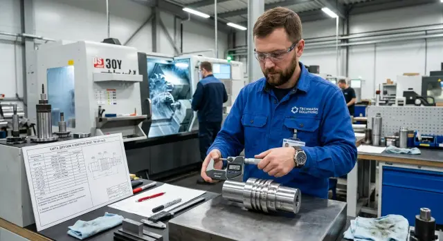
After machining, measure the dimensions in the sensitive zones: outer diameter, seating diameter, length from datum, the area near a groove or shoulder. Then let the part cool and measure again. Even a small change after cooling can change the picture. If the part is in size right off the machine but comes close to the limit after 20–30 minutes, this will be a problem in a series.
Compare the results with the tolerance map. Look not only at "pass" or "fail" but at where the margin is small and which operation it's linked to. This makes it easier to find the weak spot in the process.
Make one specific decision for each problematic area: change the regime, the tool, the fixture or the inspection. When everything is corrected at once, the real cause is quickly lost.
A practical rule: if size drifts because of heating, revise the regime. If size varies from setup to setup, check fixturing and clamping. If size slowly shifts during work, first look at the tool and its stability.
Where to place control points
Control points belong not where it's most convenient to measure, but where the part most often fails in assembly. If the trial part looks fine only by outer diameter, that doesn't mean much. Failures often come from fits, concentricity and form transitions.
First mark dimensions that determine the assembly's function: bearing fit diameter, distance between a stop and a groove, seating depth, face runout. If assembly starts to bind, have play, or wear quickly because of these, that's where control points are needed.
Also check areas near shoulders, grooves and thin walls. It's harder for the tool to hold geometry in those places. After machining these zones are likelier to show size drift, burrs, form collapse or extra taper. On a single part this is easy to miss, but in a run the issue appears quickly.
If the part is axial, don't reduce control to a single outer diameter. Diameter may be in tolerance while the axes of two surfaces don't align and the assembly runs skewed. Place points on pairs of related surfaces: on the datum diameter, the fit and the face used for reference.
Before the trial run choose measuring tools in advance. Check outer diameter with a micrometer, groove depth with a depth gauge, runout and concentricity with an indicator on a stand, internal size with a bore gauge. If access is poor or the measuring tool lacks resolution, identify that early and adjust the tolerance map.
For a simple turned part a good set of points often looks like this: fit diameter, datum face, groove width, distance between two steps and runout relative to the datum. This control gives an honest picture: whether the process holds for a series or only for one lucky blank.
Example with a simple bushing
Take a simple bushing with an outer bearing fit and a face that clamps in assembly. On the first part everything looks calm: the fit diameter is within tolerance, surface finish is fine, runout is acceptable.
But things that are often missed surface later. The outer diameter has its own behavior and the face affects the overall length. If the operator checks only the fit, they may think the process is ready. In reality the run may already be near the limit.
Suppose the drawing calls for a fit diameter of 40.000–39.985 mm and a total length of 32.00 ±0.03 mm. The first part measures: diameter 39.992 mm, length 32.02 mm. Formally OK. But the length is already close to the upper limit and the margin is almost gone.
After a few parts the insert wears. The diameter still holds while the face slowly drifts. On the fifth part the length is 32.04 mm. One or two more parts and the length will be out of tolerance, although looking only at the diameter the process still seems stable.
The tolerance map helps here. It prevents evaluating dimensions in isolation. From the first five parts you see that the diameter fluctuates in the middle of the tolerance while the length creeps upward. That indicates behavior of the process, not a random miss.
For such a bushing three control points are usually enough: the bearing fit diameter, the overall length from the datum to the face, and the dimension from the locating shoulder to the clamping face. That is enough to notice early where the run will start to fail.
Common mistakes before starting a batch
The first and most common mistake is treating one good part as proof of stability. On the trial the tool hasn't worn, the machine may not be in the same thermal regime, and the operator works more carefully than later in normal pace.
The second mistake is measuring only immediately after machining. Metal cools and stresses redistribute, and a small shift can matter for tight fits or thin walls. For a loose part this is harmless, but for a tight fit a few hundredths change the result.
The third mistake concerns measurement datums. When dimensions measured from different datums get mixed in one table, numbers look tidy but conclusions are false. One size checked from the face, another from a shoulder and a third from the chuck—then it's unclear where geometry really shifts.
Another problem is focusing only on numbers and missing process behavior. Vibration marks, waves on the surface, and shifts after a tool change often appear before a dimension goes out of tolerance. If these are missed, the run will pass measurements at first, then start drifting.
Finally, critical dimensions that affect assembly are sometimes left unchecked. Outer diameter and length are measured but the bearing fit, concentricity or distances between datums are not. The part is then "in tolerance" on paper but fits the assembly tightly or with skew.
Before the first batch, a few simple actions usually suffice: check 3–5 parts in a row, repeat measurements after cooling, record dimensions from the same datums, separately monitor critical sizes and agree in advance what to do at the first sign of drift. This approach is far cheaper than troubleshooting scrap after a run starts.
What to do after the trial run
Even if the trial part is within tolerance, the check doesn't end there. Produce a few more parts at the same regimes. For a simple batch 5–10 pieces are usually enough. Then compare the spread for sizes nearest the tolerance limits and also review geometry, surface finish and fixture repeatability.
If the first part was near the center of the tolerance and subsequent parts moved toward the edge, that's a clear signal: the process works but has little margin. In production such a setup often starts to drift due to warm-up, tool wear or not-very-rigid tooling.
After the trial run it's useful to prepare a work sheet. Include cutting regimes and program number, tool and offsets, measurement order, dimensions for full and sampling control and the conditions that make the operator stop the process. When this sheet is next to the machine, the next start is calmer and less guesswork is involved.
If the margin is small, don't hope it will "hold somehow" in production. It's simpler to check clamping, tool overhang, holder condition, fixture rigidity, sequence of passes and the operation itself right away. Sometimes the issue isn't the setup but that the dimension is being held at the limit of the current machining scheme.
If the process looks unstable at this stage, involve outside specialists. This is appropriate when the challenge concerns machine selection, launching a new operation, commissioning or service. In such cases discuss the problem with EAST CNC. The company works with CNC turning machines and helps with selection, commissioning and maintenance, so this review makes sense when the question touches the whole machining scheme, not just the part.
A good outcome of a trial run looks simple: several parts in a row give similar results, the control scheme is clear, operating modes are recorded, and the margin of accuracy is visible not on a single part but on a short series.
FAQ
Why is one trial part not enough?
Because one part only shows a single successful setup. A production run evolves: the machine heats up, the tool wears, the clamp changes how the blank sits, and the size drifts toward the tolerance limit.
How many parts should you make before starting the run?
Usually 5–10 parts in a row at the normal rhythm, without manual adjustments after each cycle. This run quickly shows whether the process holds size and form or the first part was just lucky.
What does margin of accuracy mean in simple words?
It's the distance from the actual size to the nearest tolerance limit. The larger this margin, the more confidently the process tolerates heating, tool wear and the usual cycle-to-cycle variation.
When is the best time to measure a trial part?
Measure immediately after machining, then repeat the measurement after the part cools. If the size shifts noticeably after cooling, the same issue will appear quickly in production.
Which dimensions should be included in the tolerance map?
Include only sizes that affect assembly and function: fits, lengths from bases, runout, concentricity, dimensions near steps and grooves. Small chamfers and secondary features can be left out if they don't matter.
Where should control points be placed on a turned part?
Place them where the assembly most often starts to stick, loosen or wear. For a turned part, that's typically the mating diameter, reference face, distance between steps, groove size and runout relative to the base.
What to do if the size drifts after the machine heats up?
Check cutting regime and the machine's thermal behavior. If the size consistently drifts after warm-up, review speed, feed, cut depth and the sequence of operations, then run several parts again.
Why does size vary from setup to setup?
Most often the cause is fixturing and clamping. Check jaws, stops, cleanliness of support surfaces and the repeatability of part location—otherwise even a good program won't hold the batch.
Is it enough to control only diameter and length?
No. Check form, runout, concentricity, lengths from the same base and surface condition too. A part can pass on one diameter but fail during assembly because of geometry issues.
What to do after a trial run if the process is still unstable?
Record cutting modes, program number, tool and offsets, measurement order and the limits that make the operator stop the process. If, after adjustments, the process still runs at the tolerance edge, involve specialists from EAST CNC for machine, tooling or commissioning support.