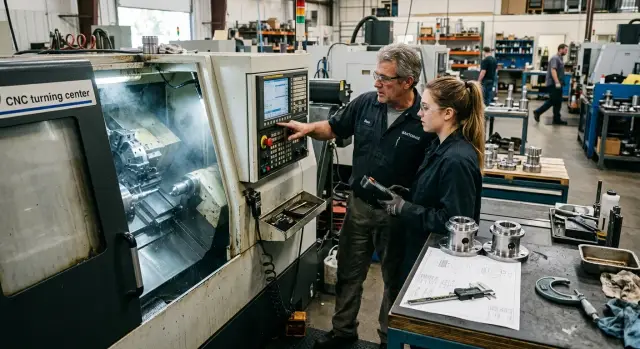
Training a Second CNC Operator on a Part Family
Training a second CNC operator on a part family: how to transfer locating, offsets, and size control without tying the learning to one program.
Why one program is not enough for training
If a second operator is trained on just one program, they learn the button route, not the job itself. Open the right number, call up the tool, press start, take the first measurement — that is easy to repeat from memory. Problems begin when a different part is loaded into the machine.
That is where the main confusion starts: a button and a skill are not the same thing. The button on the screen is the same, but the skill is different. The operator needs to understand which base the dimension comes from, where the zero point can shift, which offset to change, and after which measurement to do it. If they only know the sequence of panel actions, they are calm only in a familiar scenario.
One learned program does not help when the part changes, because the machining conditions change too. Even within one part family, the blank length, clamping method, reference surface, stock allowance, tool, and tolerance can all be different. Yesterday the operator turned a short bushing, and today they load something similar, but 20 mm longer and with a different base. Without understanding the logic, they start guessing.
At the same time, part of the work stays the same. That is what training should build on: how to check that the part is seated correctly on the base, how to connect a size deviation to the right offset, when to measure the first part, when to recheck, and how to tell a program problem from an installation error or tool wear.
This approach gives the operator room to handle different situations. They stop relying on one familiar program and start applying the same way of thinking to a group of similar parts.
A good training goal is simple: the person should understand why they do each step. Not just remember the path from button to button, but see the link between locating, correction, and the size on the part.
On the shop floor, that becomes obvious very quickly. An operator trained by logic asks short, precise questions when a new part appears. Someone trained on one program often stays silent until the first mistake, and then spends a long time trying to figure out exactly where everything went wrong.
How to choose a part family for training
A part family is better built around one machining logic than around outside similarity. If the operator loads the blank the same way, uses the same reference surfaces, and checks the same dimensions, that group is a good candidate for training.
The first filter is simple: common reference surfaces and the same clamping method. For turning, that often means one chuck, a similar overhang, the same stop, and the same zero reference after facing. If these things change a lot from one part to another, the beginner is not learning one family — they are learning several different jobs at once.
Similar drawings often cause confusion. Two shafts may look almost identical, but one is located from the faced end after the first pass, while the other is based on the seat after being flipped. For training, those are already two different scenarios. It is better to use fewer parts with one clear setup scheme than to collect a random set just for volume.
It helps to make a short family map and keep it next to the programs. Four things are enough: how the blank is loaded and where the base comes from, which dimensions are checked on the first part and later in the shift, which tool repeats from part to part, and which offsets the operator changes most often.
It is also worth noting the dimensions that hardly change within the group. That may be the base diameter, overall length, groove width, or the size after finishing. These help the second operator understand where to look first and avoid measuring everything blindly.
The same applies to tools and offsets. If the same turning tool, drill, and wear adjustment logic repeat across several parts, training becomes much easier. On series parts, repeatability is what gives you a stable pace.
It is best to remove high-risk parts from the group right away: thin-walled blanks, expensive material, a very tight tolerance on one dimension, a long overhang, or unstable chip flow. At the beginning, the operator needs confidence where mistakes are easy to see and easy to fix without big losses.
If you are choosing between two groups, take the one where the supervisor can explain the reason for each action in simple words. That is usually the right family to start with.
What to prepare before the first training shift
A training shift goes more smoothly when the operator has a clear reference on paper instead of a pile of random hints. For a part family, that is especially important: the program may change, but the logic of locating, zero checking, and recording offsets stays almost the same.
Start by preparing one locating map for the whole group. Do not make a separate sheet for every small difference. It is better to show the common setup: which surfaces the operator rests on, where the part is clamped, which end face or diameter is used as the base, and what must not be confused. If two parts differ only in length or one shoulder, the map should still remain shared. That way the person remembers the principle, not just the picture.
Next to the map, prepare a short list of key dimensions and tolerances. Not the full drawing — only the dimensions that quickly show whether the process is under control. Usually that means dimensions from the base, critical diameters, overall length, fit, and one dimension that drifts first when the tool starts to wear. People actually use a short list. Long ones usually sit untouched.
Also show exactly where the operator takes zero and how that is confirmed. The phrase “as usual” only creates trouble here. You need to say clearly which surface the reference comes from, which tool or gauge is used to verify the position, and which control dimension must match after the test part. If zero is easy to mix up, the shift can go off track right from the start.
Before the first run, it helps to ask the same set of questions every time:
- What is the base for this part?
- Where is the part zero and how do I check it?
- Which dimensions do I measure on the first part?
- Which offsets can I change myself?
- When should I stop the machine and call the setup technician?
Another useful document is a simple log for offsets and measurements. No complex tables. Five columns are enough: time, part number, actual size, which offset was changed, and who changed it. Such a sheet quickly shows the logic of the actions. If the size drifted after the third part, the operator sees a history instead of a guess.
In practice, this works better than a long explanation at the machine. By the time the first shift starts, the person already has a clear plan: how to load the part, what to check, what to record, and when to stop.
How to teach locating step by step
The second operator needs to see the logic of how the part sits, not just one familiar setup. If they only remember the jaw position from one program, the first similar part will already create mistakes.
Start with the basics. The part, jaws, stops, and support surfaces must be clean. Chips, burrs, or a drop of thick oil can easily create tilt, and the beginner will then look for the reason in the wrong place. For a training shift, it is better to use blanks with clear bases where it is easy to see how the part should seat.
The setup should be shown with hands, not just words. The operator places the part in the fixture, brings it to the base, presses it lightly into position, and only then clamps it. If you do it the other way around, the clamp will pull the part out of position, and the rest of the inspection will no longer mean much.
One fixed sequence
A steady sequence helps here. First clean the supports, jaws, and the part itself. Then seat the part against the base and stop, make a light preliminary clamp without extra force, check that the part is truly seated, and only then tighten fully and check runout.
The seat check should also be taught separately. Have the operator look not only at the indicator, but also at the actual contact between the part and the stop. Sometimes a thin strip of paper is enough: if it slides freely out of the contact area, the part is not seated correctly. This quickly breaks the habit of trusting the clamp alone.
The simplest rule works best: base first, then clamp, then runout check. That order is easy to repeat and easy to verify.
Practice without cutting
Often it is more useful to install the same part five times than to run one cycle once. Remove the part, reinstall it, and repeat the check at the same point with the same indicator. Cutting is not needed at this stage. The goal is different — to get the same seating several times in a row.
Check the result with one consistent method. If the first setup shows 0.02 mm of runout and the next one already shows 0.08 mm, the operator should not guess — they should go back to the base and check the contact surfaces. After a few repetitions, they start noticing misalignment even before the indicator. That is the skill that later transfers to the whole part family.
How to teach corrections without guessing
Mistakes with offsets almost always start the same way: the operator sees a size drift and tries to “adjust the machine” by eye. That is not the right way to teach it. From the beginning, there should be a simple distinction: tool geometry is for the initial setup, while the working offset is only for small size drift during production.
If the insert was changed, the reference was lost, the part was reinstalled, or there was a strange jump in several dimensions at once, it is too early to touch the working offset. First check the part locating, clamping, tool overhang, and the measurement itself. The correction is changed only when the base is stable, the program is the same, and the size has drifted in a predictable way — usually because of tool wear.
A good rule is: one cause, one correction, one check measurement. The operator makes one small adjustment, runs a part or a control pass, and checks the result. If they change several values at once, nobody will later know what actually helped and what only added error.
For the first training shift, it helps to set a strict limit for one correction. For example, for a finishing dimension it might be 0.01–0.03 mm if your process usually lives in that range. If more correction is needed, the operator should stop adjusting and call the setup technician to find the cause. A large correction often points not to wear, but to a problem with the base or the measurement.
It is also better not to touch several axes in a row without checking. If the size drifted in X, correct X and measure again. If it drifted in Z, work with Z. If both axes are suspected, the operator should first recheck the setup and the control dimension instead of entering two corrections in a row based on one measurement.
A short note after each correction is also useful: which part was in the machine, which size drifted and by how much, which offset was changed, by how much it was changed, and why that decision was made.
Such a log quickly shows where the person understands the process and where they are still guessing. After a few shifts, it also shows which parts drift most often, which tool wears out fastest, and where the operator confuses wear with a locating error.
How to organize size control during the shift
In series production, there is no need to measure everything. It is better to choose 3–5 dimensions that show drift before obvious defects appear. Usually that is the diameter after the finishing pass, the length from the base, the cut-off dimension, a bearing fit, or a groove if it is sensitive to tool wear.
If the parts run as a family, this set of dimensions often repeats. That is useful: the operator learns to see not one program, but the overall process logic. That is more helpful than the habit of measuring only the dimension the setup technician pointed out this time.
It is important to set exact inspection points. Not “sometimes,” but one clear rule: the first part after startup, the first part after any correction, one part after a set batch — for example after 10 or 20 pieces — and any part after a tool insert, chuck, or part change.
Then you need a simple control sheet. Next to each dimension, note what to measure it with: a micrometer, caliper, bore gauge, or indicator. It also helps to note a common mistake. For example, people over-tighten the micrometer, tilt the caliper, fail to bring the bore gauge to minimum, or check the length from a dirty reference surface.
Drawing dimension and decision dimension
The operator should distinguish between two numbers. The first is the drawing tolerance. The second is the working point used to decide whether a correction is needed. They are not the same.
A simple example: on the drawing, the diameter is 20.00 +0.02/0. A part at 20.018 is still acceptable. But if the previous part was 20.010 and the tool keeps pushing the size upward, waiting for the next part is risky. The decision to correct is made based on the trend and the working point, not on the thought “it’s still in tolerance, so no need to touch it.”
The operator should be trained to stop the run when a measurement is doubtful. If the size is only “about right,” if the measuring tool raises a question, or if the part could not be seated properly during the check, production should continue only after a repeat inspection. Losing three minutes on a recheck is better than ending the shift with a box of questionable parts.
An example of training on two similar parts
Take two shafts from the same family. They should have the same base, the same setup method, and a similar operation sequence, but a different overall length. This kind of example clearly shows that the operator needs to understand the machining logic, not memorize the program.
Let’s say the first shaft is 120 mm long and the second is 145 mm. The base journal diameter, the stop position, and the clamping scheme do not change. The operator immediately sees the key point: the base is the same, so the order of actions before startup stays the same too.
First they check how the part sits on the base, then the overhang, then the part zero, and only after that do they look at the first-pass dimensions. If this order is set correctly once, it transfers to other similar shafts with almost no confusion.
In this exercise, it helps to separate what stays the same from what changes. Usually the tool offsets working on the same surfaces remain unchanged, the order of tool calls in the program stays the same, the logic of first-pass inspection stays the same, and the base diameters and base-to-length checks stay the same.
But the overall length often changes the most. That is where the second operator usually makes mistakes: they see a familiar part and automatically leave the old offset value or the old control point in place. The diameters may still be fine, but the length ends up scrapped.
A good shift exercise is to let the operator handle a second part after the first one is set up and ask them to explain their actions out loud. Do not give hints too early. Let them say what they will check first, which dimensions they will watch most closely, and which corrections they will not touch.
If the answer sounds like this: “First I’ll check part locating, then the base dimension, then the overall length, and only after that will I adjust the correction,” then the training is moving in the right direction. The person is no longer clinging to one program number. They see the part family as a group with shared rules.
Mistakes that break skill transfer
Training usually falls apart not at the machine, but in the explanation. If the second operator memorizes the screen, buttons, and pressing order, they only rely on one familiar scenario. Change the setup, stock allowance, or base, and the person gets lost.
For a part family, you need to pass on not a “screen route,” but the logic: which base the dimension comes from, why that stop was chosen, when to change the correction, and when to recheck the measurement first.
The most common problems are a few typical mistakes. The first is when the mentor teaches the interface from memory. Then the operator remembers where to go, but does not understand why the part is located that way. On the next similar part, they repeat movements instead of making decisions.
The second mistake is changing the size after one measurement. A single reading can be ruined by burrs, chips on the seat, part heating, or a rushed measurement with the micrometer. A repeat measurement and another part from the same series are needed.
The third mistake is mixing roughing and finishing explanations together. The beginner stops seeing the difference between allowance for stability and the final adjustment to size.
The fourth is passing on what should be written down only by word of mouth. The base, contact order, tool numbers, usual correction step, and inspection frequency during the shift are all better kept on paper. Memory fails everyone.
The fifth mistake is leaving the new operator alone after the first successful part. One good part proves almost nothing. Real testing begins on the fifth part, the tenth part, and after a tool insert change.
A simple turning part shows this well. The operator gets a size 0.02 mm under and reaches for the correction. The mentor first asks them to remove the chips, seat the part again on the base, remeasure it, and check the next one. Often the cause turns out not to be the correction, but the seating or the measurement.
If training is going well, the person can explain their action in words before pressing cycle start. That is the sign that the skill rests not on memory, but on understanding.
A short checklist before independent work
Before leaving someone alone on a shift, check the order of actions, not speed. If the operator makes parts only from memory, without understanding the base, clamping, and corrections, the first small issue will derail the process.
A good sign is simple: they can calmly explain what they do and why. They do not guess and do not repeat someone else’s words — they name the reference, the control point, and the limit at which the machine must be stopped.
Before independent work, make sure of five things. The operator can show the part base without help and explain which surfaces the reference comes from. Before startup, they check the clamp with their hands and eyes: how the part sits, whether there is any tilt, whether the overhang is sufficient, and whether a jaw or stop is in the way. They know the first dimensions to check after startup — usually the size that drifts fastest and the size that immediately shows a base or clamping error. After measuring, they can make one clear correction and then measure the same area again. If the reason for the drift is unclear, they do not try to “pull the part into spec” by guesswork — they stop the job and call the setup technician or supervisor.
That minimum is already enough to keep a shift from turning into a late-stage scrap hunt. For example, on the first part the operator saw a diameter deviation of 0.02 mm. They make one correction on the right tool, machine the next part or run a control pass, and measure the same dimension again. If the size returns to tolerance, they continue. If not, they look deeper for the cause instead of blindly turning offsets.
This checklist is useful both for training a second operator and for normal shift handover. Independent work begins not when the person has learned one program, but when they can keep the process under control.
What to do next on the shop floor
Training should not stop at one part, even if the operator is already running it without mistakes. On the shop floor, it is worth building a route across the whole family of similar parts right away. Choose parts with a similar clamping method, clear locating logic, and similar control points. Then the operator remembers not just a set of buttons, but the workflow itself.
In practice, this is simple. Build a sequence of 3–5 similar parts, from the easiest to the one with higher risk on size or runout. For each part, keep a short card: base, zero, where the size usually drifts, and which offsets are adjusted most often. After each questionable case, update the locating card immediately while the memory is fresh. Once a week, the shift leader can review the correction logs and see why the operator changed values.
If a new CNC lathe is being installed on the shop floor or a new part group is being launched, it is often useful to involve EAST CNC engineers. The company operates in Kazakhstan as the official representative of Taizhou Eastern CNC Technology Co., Ltd. and helps not only with delivery, but also with commissioning, consultation, and service. In projects like this, it saves time at the start and reduces the number of common training mistakes.
The locating map should live with the work, not sit in a folder. If the operator confused a stop once, if the size drifted because the tool overhang changed, or if the first part had to be found in a different way, that needs to be added to the map immediately. After a month, notes like that significantly reduce the burden on the shift.
A weekly review of corrections also gives results quickly. The shift leader sees repeating causes: insert wear, heat, weak clamping, or an incorrect first-part measurement. Then the team fixes the real cause instead of teaching the operator to change numbers at random.
It is best to keep the goal simple and measurable. The second operator should be able to move the skill confidently between parts in the same group. A good test looks like this: give them an unfamiliar part from that family, the drawing, and the map, and have them explain the locating, choose the control points, and say which corrections to check first. If they can do that without prompts, the training has been set up correctly.
FAQ
Why can’t you train a second operator on just one program?
Because the person memorizes a button-by-button route, not the actual job. As soon as the base, clamping, part length, or zero point changes, the familiar sequence no longer helps.
How do you know parts can be combined into one family for training?
Use parts with the same setup and inspection logic. If the operator loads the blank the same way, uses the same reference surfaces, and checks the same dimensions, that group is a good place to start.
What should be prepared before the first training shift?
Prepare a locating map, a short list of reference dimensions, and a log sheet for measurements and corrections. That is enough for the operator to understand where the reference comes from, what to measure first, and what to record after an adjustment.
What is the easiest way to teach part setup?
First show the clean supports, jaws, and the part itself, then have the operator place the blank by hand in the same order each time. The operator should seat the part on the base first, then clamp it, and only then check runout.
Should part setup be practiced without cutting?
Yes, in many cases it is more useful than the first cycle. When the operator removes and installs the same part several times in a row, they learn faster what a correct seat looks like and where misalignment appears.
When can the operator adjust a correction on their own, and when should they call the setup technician?
Corrections should be changed only when the base is stable, the program is the same, and the size drifts in a predictable way. If the insert was changed, the part was reinstalled, or the size jumped sharply, it is better to stop and call the setup technician.
Which dimensions should be checked during the shift?
Usually 3 to 5 dimensions are enough — the ones that show process drift first. Most often that is the diameter after the finishing pass, the length from the base, the cut-off dimension, or a fit that is sensitive to tool wear.
Which training example best shows the logic of a part family?
A good example is two parts with the same base and different lengths. The operator can see that the setup and inspection order stays the same, while only a few dimensions and control points change.
What mistakes most often ruin the transfer of skill?
Most often the mentor teaches the screen and buttons instead of the logic, and the operator rushes to adjust a size after one measurement. Training also falls apart when the base, inspection order, and normal corrections are kept only in someone’s head instead of written down.
How do you know an operator is ready for independent work?
Focus on the order of actions, not speed. If the person can show the base, knows the first dimensions to check, makes one clear correction, and stops the machine when in doubt, they are ready to work on their own.