Toolpath Rounding in Milling: Benefits and Risks
Toolpath rounding in milling helps remove surface marks, but it can sometimes shift dimensions and radii. Let’s look at when to keep it and when to turn it off.
What toolpath rounding changes
CAM often removes sharp breaks in the toolpath and replaces them with arcs or smooth transitions. The milling cutter does not turn at a single point. It starts changing direction earlier, and the turn itself becomes gentler.
For the machine, this is usually convenient. The axes move more evenly, the feed rate does not drop as sharply, and the tool leaves fewer marks from constant speeding up and slowing down. That is why toolpath rounding in milling often gives a cleaner surface, especially on fast passes and on long contours with frequent direction changes.
The problem is that smooth motion is not the same as exact geometry. If CAM is allowed to smooth the turn too much, it starts moving the actual cut away from the model shape. On the screen, the contour may look almost the same, but the cutter no longer reaches into the corner as deeply as the drawing requires.
The difference comes from the smoothing tolerance, the transition radius, and the way the system keeps feed rate in corners. The more CAM tries to avoid slowing down, the greater the risk that it will simplify part of the geometry. On a simple outer edge, this is sometimes barely noticeable. In an internal pocket, the error shows up right away.
The first areas to suffer are the ones with very little shape allowance:
- internal pocket corners
- short sections between neighboring walls
- thin walls and narrow ribs
- areas near small radii
- tool entry and exit zones
Imagine a rectangular pocket with almost sharp internal corners. Without smoothing, the machine will slow down and try to pass the corner closer to the calculated point. With smoothing, the path becomes calmer, but extra material may remain in the corner. If there is a thin wall nearby, a gentle bypass can also change both the load on the tool and the actual wall size.
That is why you cannot leave the same setting at the default for every part. Where you need a clean mark and have enough shape allowance, it works well. Where the corner, pocket, or thin wall defines the part size, that same setting can easily ruin the geometry.
When the surface gets better
On a finishing pass, rounding often gives a clear benefit where the wall is long and the part shape is calm. When the cutter moves without sharp braking and repeated acceleration, the machine keeps a steadier motion. The metal ends up with fewer small marks that usually appear at direction changes.
The effect is easy to see on a curved contour with a smooth line. If CAM builds the path without frequent breaks, the cutter runs in almost one mode. The load on the cutting edge changes less, the cutting sound becomes steadier, and the surface looks cleaner after the pass.
This is especially noticeable on a long side wall. For example, if you machine an aluminum housing and take a light finishing pass, small streaks may remain at transitions without smoothing. They are not always felt by hand, but they are clearly visible in the light. When the toolpath is gentler, there are usually fewer of those marks.
Toolpath rounding in milling is most helpful in cases like these:
- the finishing pass runs along a long, smooth wall
- the contour has arcs and soft transitions
- stock allowance stays roughly even
- the cutter removes a small layer instead of working under heavy load
There is another advantage too. With smooth motion, the tool does not take a sharp hit at the end of one segment and the start of the next. This lowers peak load on the cutter, especially with a small diameter. The spindle runs more calmly, and the edge wears more evenly.
On a production part, that effect becomes noticeable quickly. One pass may create only a tiny difference, but in a batch it adds up. Fewer marks after machining, less localized heating, fewer random marks at direction changes.
This setting works best where the geometry itself calls for smooth motion. An outer contour with a large arc, a long housing wall, a shaped surface without sharp breaks — these are typical places where a soft toolpath often improves the surface without changing the tool or cutting parameters.
Where the geometry moves away from the drawing
The problem starts where the path needs to stay strictly on shape, but CAM tries to make the machine motion smoother. On the screen, this often looks harmless. On the part, though, the extra arc becomes not "smoothness" but a deviation from size.
Toolpath rounding in milling most often causes trouble in internal corners. If a pocket already has little room, any added arc eats into the corner and leaves an extra radius. For roughing, this can sometimes be acceptable. For finishing, especially before assembly fit, it usually is not.
Small pockets suffer for the same reason. The tool simply has nowhere to "turn around" while keeping the rounding. CAM creates a beautiful smooth path, but the actual machining area becomes smaller. As a result, the pocket ends up slightly narrower, the corner is not fully reached, and the floor near the wall may still have leftover material.
Where the error is most noticeable
The risk rises sharply near a stock allowance of just a few hundredths. If you leave 0.03–0.05 mm for the finishing pass and then turn smoothing on without checking, the toolpath can eat into that allowance before finishing even starts. Then the final pass no longer cuts evenly. Spots appear on the surface, and the size starts to drift.
Narrow ribs and thin webs are also easy to ruin. Here, even a small deviation in the arc changes the shape noticeably. The rib comes out thinner, the web becomes weaker, and the cutter may cut into the side wall more than planned in some areas.
It is also worth watching contours where assembly will not forgive an extra radius. These include fit locations, shoulders, cover seating areas, stops, and joints with another part. If the drawing calls for a sharp transition, smoothing in CAM does not "help" the part. It changes its shape.
A simple example: a rectangular pocket 20 x 12 mm with two narrow corners for a mating insert. After smoothing is enabled, the machine runs more gently and the cutting sound improves, but the insert no longer seats all the way. The reason is not the machine or the tool. The geometry was shifted by the toolpath itself.
If an area affects fit, clearance, or wall thickness, smooth motion should come second. Hold the shape first.
What to check in CAM before calculation
If CAM smooths the path by default, the program may make the motion gentler, but it is not required to preserve the size. First, look not at the "pretty" toolpath, but at the smoothing tolerance. It should be clearly smaller than the part tolerance. If a 20 mm pocket must stay within 0.02 mm, setting smoothing to 0.05 mm is a bad idea. For roughing that may sometimes be acceptable; for finishing, usually not.
At corners, check the radius that CAM adds instead of a sharp turn. The larger it is, the smoother the feed and the fewer stop marks you get. But on internal corners and narrow slots, an extra radius quickly eats away geometry. This is especially noticeable on small parts, where even 0.2–0.3 mm shows up in the size.
It is better to separate roughing and finishing settings. Smoothing often helps in roughing: the machine shakes less, the tool lasts longer, and chip evacuation is more even. On finishing, the same values can ruin the edge or shift the wall. It is better to keep a separate CAM template for each type of pass rather than one checkbox for everything.
At walls and the floor, smoothing should be limited or turned off where the stock allowance is already zero. Otherwise, the path will gently "cut off" a corner where the drawing requires a straight intersection of surfaces. This often shows up in pockets, cover fits, and support faces.
Another common mistake is when the tool in the CAM database does not match the one actually mounted in the spindle. A couple of hundredths difference in diameter, a long stick-out, or a weak holder can change the result. With a long cutter, even a safe amount of smoothing can cause deflection and leave a mark on the wall.
Before calculation, four checks are usually enough:
- the smoothing tolerance is smaller than the part size tolerance;
- the corner radius does not enter areas where a sharp internal corner is needed;
- roughing and finishing have different smoothing rules;
- the tool diameter, working length, and stick-out match the actual setup.
Toolpath rounding in milling works well only when it serves the part, not the default setting. A few minutes spent on these checks often saves a recalculation and an extra machine pass.
How to check the toolpath step by step
It is better to check toolpath rounding in milling not by the overall look, but by a few risk points. On the screen everything may look smooth and neat, but the part is not cut by the picture — it is cut by the actual path of the tool center. Even if the CAM settings for milling are left at default, it is worth opening them and reviewing the questionable areas manually.
The easiest way is to go in this order:
- First zoom in on areas with small radii, sharp corners, narrow slots, and transitions between walls. That is where smoothing most often changes the shape more than it seems in the overall view.
- Then compare the tool center path with the model geometry. If the center moves wider in an outer corner or cuts deeper in an inner one, the surface will almost certainly drift away from the drawing.
- After that, run the simulation and look at the deviation in these exact places. Do not look only at the color map. Look at the number: 0.02 mm may be fine for one surface, but for a fit it is already scrap.
- Then calculate a separate finishing pass without smoothing. The same tool, feed, and stock allowance give a fair comparison. This shows what the function changes, not the whole cutting mode.
- Finally, compare the time savings with the size risk. If smoothing saves 10–15 seconds but adds a few hundredths on a critical edge, that gain is usually not worth it.
A good quick test is simple. Take one questionable area, such as an internal pocket corner, and overlay two toolpaths: with smoothing and without it. If the difference is visible even at a magnified view, the part will almost always see it after finishing too.
There is another common mistake. The operator looks at the part contour, not the tool axis. But the cutter cuts with its diameter, so even a small shift in the center changes the final radius and wall position. On CNC machines for metalworking, this check takes just a few minutes and often saves extra hand finishing, a repeat pass, and arguments with quality control.
Example on a simple part
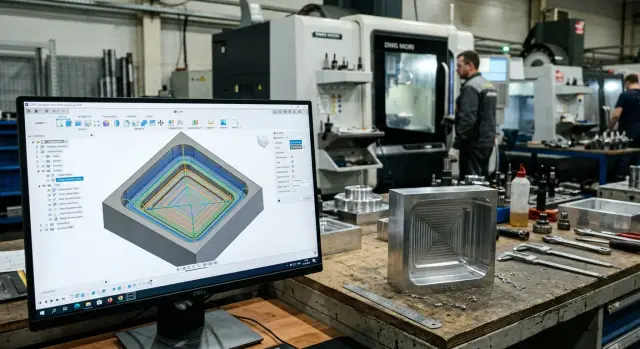
This is easy to see on a simple part: a plate with a pocket, two holes, and one internal corner where size is held by the finishing contour. For this kind of work, toolpath rounding in milling is often enabled in CAM by default. It is easy to miss, especially if the programmer uses a ready-made operation template.
The part looks ordinary. First the pocket is machined, then the walls are finished, and after that two holes are drilled. In simulation everything looks fine: the motion is smooth, with no sharp breaks, the machine should run more softly, and the wall surface usually comes out better.
On the first part, that is exactly what happens. The pocket wall comes out cleaner, the marks from direction changes are fewer, and the cutting sound is steadier. But after measurement, a problem appears: the internal pocket corner is opened slightly wider than the drawing allows. Not by much, but enough for the size to fall out of tolerance.
The reason is simple. CAM smoothed the transition in a place where the path needed to hold the shape precisely. For roughing, this is often not a problem. For a finishing contour, it is a risk. The machine moves more gently, but it removes metal not quite where it should in the corner area.
The holes, meanwhile, stay in place and raise no questions. That is why the error is confusing: the operator sees a good surface and first suspects the tool, runout, or feed rate. But the issue is not the cutter — it is the toolpath setting.
The fix is usually simple. The operator keeps smoothing on roughing passes and turns it off only on the pocket finishing contour. After recalculating the program, the corner returns to size, and the wall still looks fine. Yes, the motion becomes a little sharper, but only on a short section.
The cycle time changes only slightly. If the whole part takes a few minutes to machine, the difference is often just a few seconds. This is a good example of how one CAM setting can create a nicer surface finish and at the same time ruin geometry where tolerance is tight.
The most common mistakes
The most common mistake is simple: the technologist leaves the same smoothing setting for all operations. On roughing, that can sometimes be acceptable, but on finishing small features this approach quickly causes extra size drift. Toolpath rounding in milling should not be turned on out of habit. It should be checked for each area with short ribs, narrow pockets, small radii, and sharp transitions.
The second mistake is also very common: people look almost only at cycle time. If CAM shows a path that is 12 minutes shorter, that is nice. But the part may then lose a corner, face, or slot width by a few hundredths, and sometimes more. For simple fixturing, that is not always a disaster. For a bearing seat, cover, or guide fit, it is scrap even if the surface looks smooth.
Another issue is that small features are often not checked separately in simulation. The overall picture seems fine because the large contours look clean. But on a small boss, a thin rib, or a short internal corner, the path cuts away too much. CAM rarely "makes a mistake" on its own. Usually the user allowed too much tolerance and did not check what the program did in the tight area.
People also often confuse toolpath smoothing with tool radius compensation. These are different things. Smoothing changes the path of the tool center so the machine moves more gently and without sharp breaks. Radius compensation is needed to hold size based on the actual tool diameter. If these settings get mixed up in your head, it is easy to look in the wrong place for the cause: the operator adjusts compensation, while the problem sits in CAM and in the approximation tolerance.
A tolerance that is too large in the name of speed also causes many problems. On the screen the difference is almost invisible. On the part it shows up as a dropped corner, a bloated radius, or a wave on the wall after finishing.
Typical warning signs are:
- short elements in the toolpath disappear or are noticeably simplified;
- internal corners become wider than the model;
- the size drifts after finishing with no clear reason;
- the simulation looks smooth, but section checks show deviation;
- the operator has to keep adjusting compensation to catch the size.
If these signs appear regularly, the problem is rarely the machine. More often, it comes from treating one CAM setting as "universal."
Quick check before startup
Before sending the program to the machine, spend 3–5 minutes on a short check. Toolpath rounding in milling often removes jolts and makes the cutter mark more even, but on the same part it can also eat into a corner or shift the size by 0.02–0.05 mm. That is already enough to make the finishing pass pointless.
First, separate the areas where shape matters more than smooth motion. Sharp internal corners, narrow pockets, fit surfaces, and walls held to hundredths should be checked separately. If the drawing requires a sharp corner or exact contour, do not leave smoothing on just because it is enabled in the template.
Check in order:
- Are there internal corners on the model that must not be rounded, even slightly?
- Where are the dimensions with tight tolerances, especially on finishing walls and fits?
- Which passes did you leave as roughing, and which as finishing? The CAM settings for milling often need to differ for them.
- Does the contour in simulation match the model at corner entries, exits, and short radii?
- Can smoothing be left only on long, safe sections where it does not affect geometry?
After that, run simulation not on the whole part at once, but by operation. That makes it faster to see where CAM cuts a corner, hides an extra arc, or shifts the tool at a transition. If the contour drifts in only one place, there is no need to turn the function off everywhere. Often a simple adjustment is enough: remove smoothing on the finishing pass, reduce the approximation tolerance, or split the toolpath into two operations.
It is useful to compare two versions of the same operation. Leave smoothing on in the first one and turn it off in the second. The difference is usually clear right away: either the surface finish in milling improves without losing shape, or the part geometry starts to drift. In the second case, it is not the feed or the spindle. The error sits in the toolpath.
What to do next in your shop
It is better not to argue about the value of smoothing by instinct. Make two versions of the same program: in the first, keep toolpath rounding in milling; in the second, turn it off or lower the tolerance. Then compare not only the surface appearance, but also the size, corner shape, radii, and cycle time. After that check, the conversation on the shop floor is usually much shorter.
Looking only at roughness is not enough. A part can look cleaner but drift away from the drawing at transitions, in pockets, or near a thin wall. So check the simple pair: what happened to the surface and what happened to the geometry. If one improved and the other drifted, the setting is not right for that group of parts.
A working rule for similar parts
One good result proves nothing yet. It is more useful to write a short rule for similar parts: for example, where smoothing can stay on roughing, and where it is better to limit it by tolerance or remove it completely on finishing. Such a rule saves more time than redoing the setup from scratch on every order.
A good practice is to keep separate CAM templates for roughing and finishing. These operations have different goals. In roughing, smooth motion and stable tool load are often more important, while in finishing the exact contour and predictable size matter more. When both modes sit in one template, mistakes happen more often than you think.
If parts of the same type repeat often, keep a simple observation table. It is enough to note the material, tool, smoothing tolerance, actual size, and the operator’s comments after the first run. After a few jobs, it becomes clear which CAM settings for milling are stable and which create a nice simulation and extra problems on the machine.
Sometimes the cause is not only in CAM. If the machine lacks rigidity, axis dynamics, or stability during a long run, even a careful toolpath will not give a uniform result. In such cases, it helps to review the task as a whole: the part, the material, the cutting conditions, the fixture, and the machine itself. At EAST CNC, such a scenario can be reviewed in a practical way: from equipment selection to commissioning and service, directly tied to real metalworking.
A normal result for production looks simple: there is a proven test, there is a rule for similar parts, and there are separate CAM templates for different machining stages. Then the decision is made not by habit, but by the result on the part.