Set Screw in a Tool Holder: How It Throws Off Concentricity
A set screw in a tool holder can shift the tool by hundredths of a millimeter. Let’s break down where the offset comes from, what the measurement shows, and how to check the assembly before a production run.
Why It Starts with One Screw
The problem often starts not with the spindle or the holder itself. It is triggered by one set screw if it presses on the shank from the side instead of clamping it along the axis. From the outside, everything may look normal, but the tool is already sitting differently from how it should.
The screw is small, but its force is concentrated. It does not spread the load across the whole surface; it pushes the shank to one side. If the fit is tight, the shift may be very small. But at the overhang, even a few hundredths quickly turn into noticeable tool runout.
That is why holder concentricity drifts before the operator sees obvious scrap. On a short tool, the deviation is almost invisible. On a long overhang, those same few hundredths already leave marks on the surface, add noise, and throw off the size.
The worst part is that the first part often looks fine. The size is within tolerance, the surface raises no questions, and the process seems calm. But that calm is misleading. A shifted tool cuts at an angle, the load on the cutting edges is uneven, and after a few parts the picture changes.
Usually the spread grows first. One part passes, the next one is already close to the tolerance limit, and then a noticeable drift appears. If the batch is large, the problem builds up gradually: the tool heats up, the edge wears faster, and the shift has a stronger effect.
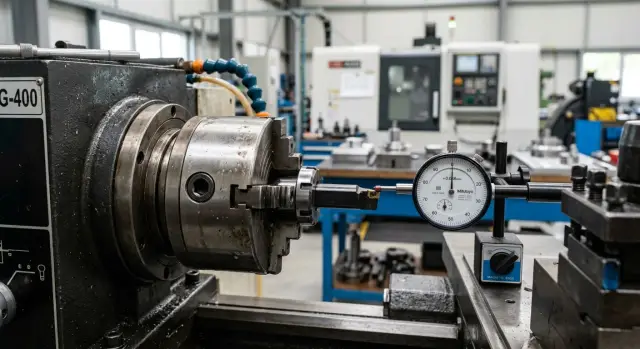
An indicator check catches this earlier than scrap. All you need to do is rotate the holder and watch how the tool behaves around the circumference. If the needle shows runout, the cause is often not the geometry of the tool itself but the way the screw clamped it.
The operator may install the holder, tighten the screw a little harder than usual, and start the machine. The first part comes out acceptable, so the setup is left alone. But after a few cycles, runout starts showing up in the size and surface finish.
That is how one screw becomes the starting point for the whole problem. It changes the tool position by fractions of a millimeter, and the machine then repeats that error exactly on every part. That is why it is better to check before scrap appears, right after assembly, while the indicator still shows the cause rather than the result.
How the Screw Shifts the Holder
A set screw rarely seems like a serious source of error. But it presses on one point, not around the whole circumference. Because of that, the holder is not just fixed in place, it is pushed off center.
If the fit is already less than perfect and there is even a small clearance, the screw uses that play like a lever. It presses the holder against the opposite wall, and the center shifts. The larger the clearance, the more noticeable the offset.
The problem gets worse when the screw is tightened with extra force. Heavy tightening does not make the assembly more accurate. It only pushes the holder farther to the side, and sometimes tilts it slightly too if the contact is on an edge or on an old dent.
In practice, this shows up right away. The operator installs the holder, tightens the screw, then checks runout. The indicator does not show random scatter, but a steady offset in one direction. If you loosen the screw and seat the holder again, the picture often changes.
The mark left by the screw also tells you a lot. A fresh dot, streak, or dent almost always shows the direction in which the screw pushed the part. It is not a precise measuring method, but it is enough for a quick check. The mark makes it easy to see where the contact is too harsh and where the holder is not seating properly.
Most often, the shift appears because of several small things at once: the screw presses against a round surface with no flat spot, there is wear or dirt in the seat, the holder did not sit all the way in, and then the operator gave the screw another quarter or half turn after the first contact.
Even a small offset quickly turns into noticeable runout at the tool overhang. If the holder shifted by a few hundredths near the base, the value will become even larger at a long tool. That is why the problem is usually seen on the indicator before it becomes scrap across the batch.
On CNC lathes, this effect is especially troublesome in production runs. The first part may still come out to size, but after that the diameter, surface finish, and fit start to drift. The reason is barely visible: just one screw pulling the holder the wrong way.
If the indicator shows the same offset in the same direction every time after assembly, look not for a random error but for the clamping point. In most cases, that is where the problem is.
What the Measurement Shows Before Scrap Does
You can usually see the problem on the indicator before you see it on the part. While the size is still within tolerance, the holder is already showing that it is being pulled sideways.
The first sign is increased runout at the overhang. Near the seat, the value may still be acceptable, but closer to the end of the holder it grows noticeably. That happens because even a small tilt at the base becomes larger over distance.
There is also a simple test. You set the holder, rotate the assembly, and get one value. Then you slightly tighten the set screw, and the needle immediately moves to another number. If one small tightening changes runout by several hundredths, the issue is no longer the measurement but the clamping itself.
What often raises concern is not just the size of the number, but its instability. You remove the holder, reinstall it, tighten it with the same force, and the result is different. Today it is 0.01 mm, after a reinstall it is already 0.03 mm. For a proper fit, that is a bad sign: the assembly seats a little differently every time.
Usually the pattern looks like this: the holder shows only a small runout near the body, the value grows at the overhang, the number changes right after the screw is tightened, and reinstalling the holder does not give the same result.
On the part, the effect shows up with a delay. The first few cycles may go smoothly, especially if the cutting conditions are gentle and the tolerance is not too tight. Then the assembly heats up, the load repeats, the tool starts working with the same offset on every pass, and the size begins to drift. At first you see it in the spread, then in a steady shift in one direction.
A good example is boring or finishing a hole. On the first inspection, the part still passes. On the third or fifth, an extra hundredth or two appears. The operator looks at tool wear, although the cause often comes earlier: the holder was pulled by the set screw, and that was already visible on the indicator before the batch started.
If the measurement changes after one extra tightening and reinstalling does not give the same numbers, do not wait for scrap. The assembly is already acting unstable, even if the first parts still look fine.
How to Check the Holder
It is best to check before the first part. That way you immediately know whether the set screw is pulling the axis off center or whether the problem is in the seat, the shank, or the screw itself.
Even a tiny chip between surfaces changes holder concentricity. Later the operator sees runout at the overhang, while the cause is already hidden inside the assembly.
Check procedure
-
Clean the seat, the shank, and the screw. Remove chips, dirty oil, and small burrs. If the tip of the screw is damaged or an old tightening mark remains on the shank, note it right away.
-
Seat the holder in place without heavy tightening. It should sit evenly, without tilt or a jerk. Make the first indicator check at this stage. If the readings are already bad here, full tightening will not fix them.
-
Check two points. First, take readings near the base, close to the seating area. Then move the indicator to the overhang. If the base is almost zero and the deviation grows farther out, the assembly is being pulled unevenly.
-
Tighten the screw in small steps. It is better to go by a quarter turn or even an eighth of a turn than to crank it down all at once. After each step, repeat the check at the same two points and write down the numbers.
-
Compare the result before and after tightening. If the readings near the base hardly change, but the runout at the overhang grows, the screw is shifting the holder sideways. If the deviation increases everywhere at once, look for dirt, a burr, or damage on the seat.
This order gives you a clear picture. You do not just see that the holder runs out; you understand when it moved and what caused it.
A small example: before tightening, the indicator shows 0.003 mm near the base and 0.008 mm at the overhang. After careful tightening, the base stays at 0.004 mm, while the overhang jumps to 0.025 mm. That kind of gap is rarely random. It is usually a direct sign that the screw moved the shank during clamping.
Mistakes often start with hurry. The operator measures only the overhang, immediately tightens the screw all the way, or places the indicator in a slightly different spot each time. In the end, there are numbers, but they are no longer easy to compare honestly.
If the readings get worse after tightening, do not start the batch. Loosen the screw, clean the seat again, check the mark on the shank, and repeat the measurement the same way. Those two minutes usually cost less than searching for the cause of scrap after a run.
Example Before Starting a Batch
Before a batch of bushings, the setup technician installs a different holder on the CNC lathe and makes the usual indicator check. Before the final tightening, everything looks calm: the needle moves within tolerance, the seat is even, and the alignment raises no questions.
The problem appears at the moment many people treat as a formality. The technician tightens the set screw, rotates the assembly once more, and sees different numbers. It may have been 0.006 mm, and now it is 0.025 or 0.03 mm. For a rough operation that may seem acceptable, but for a batch of bushings this shift is already dangerous.
From the outside, everything still looks normal. The holder sits firmly, the tool does not wobble, and there is no strange noise. So there is a temptation not to touch the assembly: if the first parts come out to size, then work can continue.
That is often what happens. The first few bushings pass diameter and length control, and the operator relaxes. But after a while, taper appears on inspection. Not strong and not immediately obvious — the kind that is first blamed on feed, insert, or material.
The logic is simple. When the screw pulls the holder sideways, runout does not always produce obvious scrap on the first part. On a short bushing, the deviation may almost disappear. Then load, heat, and cycle repetition are added, and the offset starts to show across the full length of the cut.
In such a case, it is better not to guess, but to repeat the check in the same spot and in the same sequence: measure runout before tightening the screw, tighten it to working force, check the same diameter and the same base again, then loosen only that screw and compare the readings. If the increase repeats every time you tighten it, the cause is close by.
Not the insert, not the program, and not the material. One screw changes the holder position by hundredths, and on bushings those hundredths quickly turn into taper and batch variation.
This example shows well why the indicator is often more honest than the first acceptable part. A part may pass inspection by chance, especially if the sample is small. The indicator immediately shows that the assembly shifted after tightening.
That is why, before starting a batch, it is worth spending one more minute checking again after the final tightening. Very often, holder clamping mistakes are looked for too far away, even though the cause sits in one fastening point.
Where People Most Often Make Mistakes During Assembly
The first common mistake is tightening the screw all the way at once. The mechanic wants a firmer clamp, but gets side force instead. The holder shifts slightly, and concentricity is lost before the first cut. You can barely see it by eye, but the indicator already shows extra hundredths.
The second mistake is checking only near the base. There, runout may look acceptable because the section is short and stiff. But at the overhang, the picture changes. The farther the measurement point is from the base, the easier it is to see that the holder has been pulled to one side.
Another miss is not checking how the shank actually seated in the holder. If there is dirt, a burr, or a mark from an old clamp on the contact surface, the part is no longer lying flat. The screw only makes the tilt worse. Sometimes people spend hours looking for the problem in the plate, tool holder, or chuck, although it is sitting in a tiny contact spot on the shank.
Assembly most often goes wrong because of a few habits: the screw is tightened in one motion without a smooth seat, runout is checked only near the base, the shank is not cleaned before installation, and after removal and reinstallation no repeat measurement is made.
The last point often settles the argument in a couple of minutes. If the readings change after reinstalling, the cause is almost always in the assembly, not in the machining itself. This is especially important before a run, when scrap has not started yet but the indicator already shows that the holder seats inconsistently.
In practice, it can look like this: near the base, the indicator shows an acceptable value, while at the overhang the needle moves much farther. The operator changes the insert, checks the cutting conditions, looks at the chuck, but the problem does not go away. Then the holder is removed, the shank is cleaned, the screw is tightened smoothly, the holder is mounted again, and the result changes. That means the cause was in the assembly.
In service work with CNC machines, these little things come up all the time. For companies that work with turning tooling every day, like EAST CNC, this is a common reason for extra hours spent searching for the fault. In their blog at east-cnc.kz, they often discuss exactly these practical issues: where the mistake looks small, but on a production run it quickly becomes expensive.
What to Check in 2 Minutes
Two minutes before startup can often save an entire batch of parts. If the set screw is pressing the shank unevenly, the problem is almost always visible before obvious scrap appears.
A quick inspection is best started not with the screw itself, but with the surface it presses against. Even a tiny burr on the shank changes the seat. The screw hits the high spot, the holder shifts slightly, and the indicator immediately shows extra hundredths.
Check five things:
- Run your fingernail along the shank at the contact area. If your finger catches, there is already a burr or dent there.
- Measure with the indicator before and after tightening. If the runout changes noticeably, the screw is not clamping — it is pulling.
- Look at the screw mark. A clean contact patch is better than a narrow scratch at the edge.
- Remove the holder and install it again in the same assembly. If the second measurement does not match the first, the seat is behaving inconsistently.
- Check the overhang with a ruler or stop. If it changes after retightening, the assembly is not holding position the same way.
People often do not look at the screw mark at all, and that is a mistake. It quickly shows how the load is going. If the imprint is shifted to one side, the screw is pressing at an angle. If the mark is torn, the surface is already damaged, and each new clamp will seat the holder slightly differently.
There is also a simple trick: do not tighten the screw all the way right away. First seat the holder, snug it slightly, check runout with the indicator, then tighten fully and compare the readings. If the needle moves after final tightening, the source has already been found. The problem is not the part and not the spindle, but the clamping.
In practice, it looks simple. The setup technician installs the holder and gets 0.01 mm. After final tightening, it becomes 0.04 mm. He removes the assembly, cleans the contact spot, removes the burr, installs it again, and gets almost the same reading as before tightening. That small step often solves the issue faster than a long search through the whole chain.
If even one of these checks fails, there is no point starting machining and hoping for the best. A quick inspection, reinstalling the holder, and one more control measurement take less time than checking ten finished parts after the shift.
What to Do Next
If the shift repeats even after careful assembly, do not try to force the assembly tighter each time. That only hides the cause and adds new stress to the seat. First check the screw itself, then the geometry of the holder and the condition of the seating surfaces.
Screws often have simple but unpleasant defects: a battered end, signs of tilt, dirt in the thread, or uneven tightening. If it does not press along the axis or catches the part at one point, the holder will be pulled to the side again and again. Even a new screw will not help if the hole for it has shifted and the seat already has signs of crushing.
Then compare the clamping method with the working conditions. A short overhang and moderate load forgive more. A long overhang, a heavy tool, interrupted cutting, and high speeds quickly expose the weak spot. If the assembly is already working at the limit, replacing the screw alone will not solve it.
Before a run, it helps to set a simple routine: define the allowable runout for the operation before the batch starts, take a measurement after assembly and after a trial cut, record the result, and stop immediately if the value goes out of tolerance, even when the part still looks fine.
This approach saves both the tool and the setup technician’s time. Scrap in a batch almost always shows up later than the first bad measurement. If you wait only for an obvious mark on the part, you can lose a whole shift searching for the cause.
Another sensible step is to look at the assembly as a whole. Check whether there is wear in the taper, a bruise on the seat, signs of rotation, and poor repeatability after removal and reinstallation. Holder concentricity rarely drifts on its own. Usually there is a specific mechanical reason, and it can be found fairly quickly.
If the problem repeats on different operations or you are choosing equipment for such conditions, it helps to discuss the task with people who set up machines for production. EAST CNC supplies CNC lathes and machining centers, and also helps with selection, commissioning, and service. In such cases that is convenient: you can look not only at the machine, but at the combination of tooling, cutting conditions, and real accuracy from the very start.