Reverse Turning from the Shoulder to the Chuck Without Vibration
Reverse turning from the shoulder toward the chuck can reduce risk, chip issues, and vibration on difficult transitions. Let's look at when this approach makes sense.
Why the surface gets worse at a shoulder
At a shoulder, the cutting tool enters the metal in the most awkward place. The part section changes abruptly there: one side is a rigid section, and right after that there may be a thin neck. The tool has only just touched the workpiece, and the first mark already appears at the transition. If feed and cutting conditions are set right on the edge, that mark remains in the finishing zone and is then hard to remove with one light pass.
The problem is often created not by the shoulder itself, but by the way the chip behaves. In a normal pass, the chip curls near the step, hits the shoulder wall, and returns to the already machined surface. After that, it is simple: the chip rubs the metal, leaves scratches, and spoils the surface finish. On stainless steel and gummy steels, this shows up especially fast because the chip is longer and more likely to stick to the cutting zone.
There is another unpleasant issue. When the tool approaches a thin section, the part is already holding the load less securely. Even a small force starts to make the workpiece move, and chatter appears. At first you hear a light ringing sound, then a fine wave shows up on the surface. If the operator keeps the pass going at the same settings, the wave grows with each revolution.
A long overhang makes all of this worse at once. The workpiece behaves like a spring: it sits rigidly at the chuck, but farther from the jaws it moves away from the tool more easily. Because of this, the same settings give a normal mark on a short part, but on a long part they leave ripple, bands, and tearing near the shoulder.
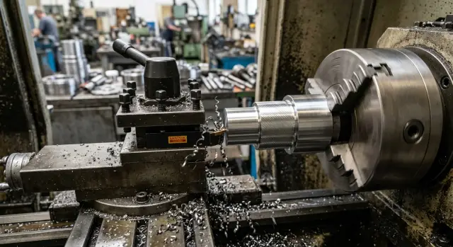
On a stepped shaft, it usually looks like this. The tool moves toward the shoulder, removes stock, then the chip runs into the step, does not break right away, and slides over the already finished land. At the same moment, the thin neck deflects slightly, and instead of a straight line the tool writes a fine wave.
That is why reverse turning from the shoulder toward the chuck can sometimes produce a better surface. The tool does not start the pass right on the transition, the chip moves into a freer area, and the load on the thin section is distributed more calmly. It is not a universal method, but on parts with a shoulder, a thin neck, and a long overhang, the cutting direction often matters more than a small change in speed or feed.
When feeding toward the chuck helps
Feeding toward the chuck is useful when a normal pass ruins the area near the shoulder. When cutting toward the clamp, the cutting force often acts more calmly: the part is supported by the chuck instead of trying to move away from it. This is especially noticeable on a finishing pass, where even a small deflection is immediately visible in the tool mark.
If the workpiece flexes a little, the cutting direction changes how the part behaves more than it seems. With a feed toward the chuck, the neck deflects less away from the tool, so the pass runs more smoothly. It is easier to hold the size near the step because the tool is not "catching up" with a weakened section; instead, it approaches a stiffer area.
There is a second advantage too: the chip is more likely to move away from the already machined surface. When the pass goes from the shoulder toward the chuck, the chip less often rubs the finished neck and does not wrap as often in the very place where you need a clean mark. For stainless steel, gummy steels, and long continuous chips, this often gives a noticeable difference in surface appearance.
In practice, this helps in four typical cases:
- ripple appears quickly near the shoulder;
- the finishing size "drifts" right at the step;
- the chip catches the already turned neck;
- during a normal pass, you hear a light ringing sound before the shoulder.
Reverse turning from the shoulder toward the chuck is also useful when you only need to remove a very small amount of stock. On such a pass, the tool is no longer fighting a large layer of metal, and the change in direction gives a clean effect without extra disturbance. If a CNC machine is set up correctly, the operator can more easily repeat the same result part after part.
On CNC lathes used in serial metalworking, this is often used for steps with high surface finish requirements. For example, a shaft has a short neck before the shoulder. With a normal feed, a fine wave appears in the last few millimeters. After changing direction, the mark becomes smoother, and the size at the step no longer drifts by a few hundredths.
This approach does not solve every problem by itself. But if the cause is deflection of the part, chip behavior, and a weak section near the shoulder, feeding toward the chuck often gives a calmer pass from the very first try.
When it is better to keep the normal direction
The normal direction often wins not because of habit, but because of the simple mechanics of the process. If the workpiece is short and rigid, it cuts comfortably in both directions. In that situation, reverse turning from the shoulder toward the chuck often gives no clear advantage, and sometimes it only adds extra setup details.
The most common case is a short step or a bushing clamped close to the cutting area. The part does not flex, the tool does not pull away, and vibration in turning hardly grows. If the surface already comes out clean, there is no real reason to change the cutting direction.
A problem can appear at the chuck. When the feed moves toward the jaws, chips are more likely to collect in the tight area in front of them. They scratch the already machined surface, reduce visibility, and sometimes wrap under the edge. This is especially noticeable with long curly chips. The normal direction carries the chip away from the jaws, and the operator can keep the process under control more easily.
Tool geometry also matters. Not every tool exits the cut cleanly when it moves toward the chuck. The approach angle, tip radius, and tool holder shape can leave a small mark at the end of the pass. On a part with strict surface finish tolerances, such a mark can quickly become a reject.
Another practical point is the program. With the normal direction, it is easier to make a clear approach and a safe retract. The path is shorter, the exit area is freer, and there is less risk that the tool will linger near the jaws or hit an awkward allowance.
The normal direction is usually kept in these cases:
- the part is short and cuts without chatter
- chips tend to collect near the jaws
- the tool does not exit the cut well at the chuck
- the program already gives a clean and safe retract
A good example is a short stepped shaft with a small relief near the shoulder. If the machine cuts it calmly and the surface is already smooth on the standard pass, it is better not to complicate the path. Reverse passing is not always helpful. Sometimes the most stable and clean result comes from the normal direction.
Which parts benefit most
This pass works best where the shoulder sits close to the finishing zone. If the tool moves in the normal direction, it often leaves its mark in the most visible place: at the step, on a seating edge, or on a thin neck that is already prone to chatter.
The effect is most noticeable on these parts:
- stepped shafts where the finished neck comes almost right up to the shoulder
- bearing seats next to a step
- long thin sections that start ringing in the normal direction
- surfaces where no scratch is allowed at the tool entry point
On a stepped shaft, the problem is usually simple: the size is correct, but the surface at the shoulder gets damaged. The tool approaches the step, the chip breaks less cleanly, and a mark appears in the last few millimeters. If the technologist changes the cutting direction, the tool moves away from this sensitive area, and the finished neck often comes out smoother.
The effect is even more noticeable on bearing seats. There, not only the size matters, but also the condition of the surface right at the step. Any scratch, dent, or small buildup can interfere with fitting later. Reverse turning from the shoulder toward the chuck helps remove the entry mark and pass the section more calmly, where the normal direction often damages the edge of the seat.
Thin sections often benefit too. For example, on a long small-diameter neck, the part may ring even with a light cut. With a feed toward the shoulder, vibration can increase toward the end of the pass, and ripple appears on the surface. If you go the other way, cutting is often quieter because the weakest section does not get an extra hit at the end of the pass.
There are also parts where the tool mark at entry is simply not acceptable. This happens on seal necks, on visible outer lands, and in places that will later be checked for surface finish. In such cases, it is better to start the pass from the side where a small mark is easier to remove on exit than to leave it directly in the working area.
In short, this method is not useful on every part. It is needed where the shoulder, thin wall, or strict surface finish makes the last few millimeters the hardest.
How to set up the pass step by step
First, look not at the cutting data, but at the tool path itself. If entry into the cut happens on a thin section and exit is near the shoulder, the mark on the surface often runs right to the step. With reverse turning from the shoulder toward the chuck, the picture changes: the chip leaves differently, and the tool exits the area where it used to leave ripple.
The same cutting data can behave differently just because of the feed direction. That is why a test pass is better built as a short trial, not as an immediate full-production operation on the entire size.
- Mark where the tool enters the metal and where it exits. Check this directly on the part, not from memory. If the exit falls in a place where the surface already "rings," change the direction first, and only then adjust speed and feed.
- Reduce the overhang of the part and the tool as much as the setup allows. Even 10-15 mm less often reduces vibration in turning noticeably. If the part is long, it is better to decide right away whether a tailstock support is needed.
- Choose a insert with chip flow that is predictable on your material. If the chip sticks to the edge or hits the shoulder, surface finish is usually the first thing to suffer. For a trial, do not choose geometry that is too "sharp" if the machine and clamping are not very rigid.
- Leave a small stock allowance for the test pass. It should be enough for the tool to cut steadily, but small enough that a mistake will not ruin the size. On a finishing mark, too little stock can sometimes give a false impression that the problem is gone.
- Compare the surface mark in both cutting directions. Look not only at the shine, but also at the feed line pitch, the sound of the pass, and the chip shape. If feeding toward the chuck makes the sound smoother and there is less ripple at the shoulder, that is a strong sign the direction is right.
It is useful to make two short passes on one workpiece if the stock allowance allows it. That makes the difference easier to see without guessing. In practice, the winner is not the option that only looks better at first glance, but the one that repeats on the second and third part.
If the surface became cleaner after changing direction, do not rush to speed up the cycle. First lock in the successful setup: the same overhang, the same insert, the same tool entry and exit. Only then should you gradually increase the cutting data.
Example with a stepped shaft
On a stepped shaft, this shows up very quickly. There is a bearing neck, and right after it a shoulder. After the finishing pass, circular scratches appear on the seat, although the cutting data seems normal, the insert is not new but still usable, and runout is within tolerance.
The problem often appears at the end of the pass, when the tool moves toward the shoulder. The chip does not leave freely, gathers at the step, and starts wrapping near the cutting zone. At that moment, the machine is noisier than usual, and the surface is left with a mark as if the tool vibrated for a fraction of a second. This is not always severe chatter. Sometimes you only hear a light ringing, but that is already enough to spoil the surface finish on the bearing neck.
On one such shaft, a simple change of direction helped. The settings were kept almost the same: the same depth of cut, the same feed, the same insert. Only the path was changed - from the shoulder toward the chuck. The chip came off more calmly, did not collect at the step, and the noise dropped noticeably. The tool mark became more even along the entire seat, especially in the last few millimeters near the transition.
After that, the part was measured at several points. Before, the size near the transition often drifted a little: closer to the shoulder, an extra mark would appear, and another light pass was needed. With the feed toward the chuck, the size held more evenly. The difference can be small, but on a bearing seat even a few microns can decide whether the part goes straight to assembly or back to rework.
This method works well when a short neck ends at a rigid shoulder and surface finish matters more than cycle time. For long free sections, it is not always needed. But if scratches appear exactly at the step and chips tend to gather at the end of the pass, it is worth changing the cutting direction at least once and comparing the result by sound, tool mark, and measurement after the pass.
Where mistakes happen most often
Most often, the problem is not the cutting data itself, but weak rigidity in the setup. If the jaws are extended too far and the part is clamped too short, the tool gets too much freedom to chatter. With reverse turning from the shoulder toward the chuck, this quickly ruins the surface finish, especially near the step.
The second common mistake is using too large a nose radius on a less rigid part. On paper, such a radius may give a beautiful finish, but in real work it pushes the metal apart more strongly. If the shaft is thin, the overhang is large, or the clamping is weak, you get ripple and size drift instead of a smooth surface.
Another bad habit is increasing feed after the first sign of ringing. Once chatter is already audible, feed rarely fixes the cause. Usually it only makes the mark rougher. It is better to stop, reduce the overhang, check the clamping, reconsider the nose radius, or change the depth of cut.
The shoulder deserves special attention. If a burr was left on the edge after a previous operation, the finishing pass will almost always go worse. The tool catches that area, chip formation breaks down, and a tear or matte stripe appears on the exit. A couple of minutes spent removing the burr often save a full reset.
Another mistake appears even with experienced operators: they look only at the shine. The surface may look smooth, but the size has already shifted by several hundredths. When the cutting direction changes, the load on the tool changes too, and the part can spring differently than in the normal direction. That is why after a test pass, you should measure the diameter first and only then judge the appearance.
A quick check can look like this:
- reduce the overhang of the jaws and the part as much as the part allows
- do not use a large nose radius if the clamping is weak or the part is thin
- at the first sign of chatter, do not speed up the feed; look for the cause
- remove the burr at the shoulder before the finishing pass
- check both shine and size
In practice, mistakes often pile up together. For example, a stepped shaft is clamped with a large overhang, a "soft" finishing tool with a large radius is installed, and then the operator tries to go faster when ringing starts. After that, the method gets blamed, even though the real problem was the combination of clamping, tool choice, and control.
A quick check before starting
Before the first pass, do not touch the program. First look at the part setup and the tool entry. With reverse turning from the shoulder toward the chuck, small details often decide everything: an extra 10-15 mm of overhang or an approach that is too close to the shoulder quickly leaves marks on the surface.
Start with the clamping. The jaws should hold the part rigidly, without unnecessary overhang from the chuck. If the part sticks out farther than needed for the pass, the tool can rock the workpiece more easily, and noise usually grows closer to the end of the cut. That is the first sign that the setup is operating at its limit.
Then check the entry path. The tool should not run into the shoulder during approach. Leave a clear approach so the edge takes the stock smoothly instead of cutting in with its side. On a finishing pass, this is especially noticeable: one hard entry, and the shoulder immediately gets a matte area or fine ripple.
Also look at where the chip will go. If it lands on the already machined neck, surface finish almost always drops. It is better to make a short trial pass and watch how the chip comes off during the first few seconds. If it runs along the neck or wraps near the chuck, the setup should be corrected before the main cut.
A good quick procedure looks like this:
- check that the part overhang is minimal for this operation;
- confirm on the screen and by hand that the tool enters without touching the shoulder;
- make a short trial pass and listen to the sound;
- measure with a micrometer at the shoulder and closer to the chuck.
Many people skip the last step, and that is a mistake. If the micrometer shows the same size along the length, the system is carrying the load evenly. If the size drifts toward the chuck or the sound there becomes harsher, the problem is already there: usually it is overhang, feed, edge wear, or an unsuitable cutting direction for that part.
This check takes only a few minutes, but it often saves the part before the first full pass.
What to do after the first trials
The first 3-5 parts should be judged not by one good tool mark, but by repeatability. If the surface became cleaner on one part, but ripple at the shoulder came back on the next one, the problem is not gone. You have simply landed in a narrow cutting range.
Record right away where the new method gave a real benefit. After a few days, this is easy to forget, and a short note quickly shows which parts work better with reverse turning from the shoulder toward the chuck and where almost nothing changes.
It is useful to log at least the following in the process sheet:
- part type, material, and section diameter
- where surface finish improved and where vibration in turning remained
- cutting data separately for roughing and finishing
- tool overhang, clamping method, and other setup conditions
Separating roughing and finishing is essential. After changing direction, chip formation and edge load change, so the same feed rarely gives the same result. For roughing, you can keep a more confident cut, while finishing often calls for a lower feed and a calm final pass without rushing.
Let the setup technician look not only at the numbers in the program, but also at the assembly itself. Often the cutting direction seems to be the reason for improvement, when the real reason is simpler: too much tool overhang, weak part clamping, worn jaws, or play in the tool seat. If that is not checked, a good trial result will not repeat in production.
If parts like this come up often, it is not worth saving the surface with manual adjustments every time. At that point, it is useful to talk with EAST CNC: the company offers CNC machine selection for the task, commissioning, and service support. That conversation is not about buying at any cost, but about understanding whether your current machine has enough rigidity for the process or whether the machining method and equipment should be changed.
It makes sense to launch production only when the new setup holds the result consistently across several parts. If the tool mark is even, the chip is predictable, and the operator does not have to chase the settings by ear, then the solution can be considered ready.