How to Reduce Scrap on Stainless Steel and Titanium Parts
How to reduce scrap on stainless steel and titanium parts: choose cutting parameters, change the tool in time and keep the process clean.
Why defects happen more often on these materials
Stainless steel and titanium are less forgiving than ordinary structural steel. Heat leaves the cutting zone more slowly, so the tool edge heats up faster. As a result the process can change during a run: what was acceptable a few parts ago becomes heavier loading, surface marks appear and dimensions shift after only a few pieces.
Stainless steel often produces long, stringy chips. They catch on the part, scratch the machined surface and build up on the insert. Titanium behaves similarly but overheats even quicker. The edge then cuts unevenly and parts get torn edges, scratches and unstable dimensions.
Another feature is that small disturbances show up immediately in the result. Slight runout, weak clamping, a few hundredths change in feed or poor coolant flow might be tolerable on mild steel. On stainless and titanium they’re enough to dull the finish, tear the edge, or shift a hole out of size.
Settings on these materials rarely stay perfect for an entire shift. Tool wear isn’t always gradual. At first everything is fine, then a buildup or a local chip appears and a part changes in a single pass.
In the shop it looks familiar: the first 10–15 parts pass checks, then roughness increases, chips darken and size starts to wander. The machine may still run without alarms.
A common reason for scrap is rubbing instead of cutting. If the tool rubs the surface instead of removing material, the surface work-hardens. The next pass is heavier, temperature rises further, and the defect accumulates.
So it’s not enough to find a good setting once. You need to hold it: monitor wear, chips, coolant and how parts evolve from the first to the tenth piece.
What to watch first
If you want to cut scrap, don’t look only at final sizes. On stainless and titanium early signs usually appear before a part goes clearly out of tolerance.
Most problems start with the surface. Torn marks, dull patches and material sticking to the cutting edge usually appear before a serious size shift. Initially roughness just varies from part to part. Then the insert cuts inconsistently and size slowly drifts by a few hundredths.
Don’t ignore burrs. They often look minor on edges and in holes but clearly show the regime is unstable. If burrs after finish passes grow compared to the first parts, check feed, spindle speed and the insert condition. After that, geometry and repeatability issues usually follow.
Temper colors also give a clear signal. On stainless and especially on titanium, local overheating quickly changes cutting. If you see blue, purple or dark spots on a zone, check coolant feed, contact length, tool overhang and chip evacuation. Such discoloration almost never appears by accident.
Watch for vibration separately. On thin walls and long passes it leaves waves, a broken surface pattern and a characteristic noise. Size may still be within tolerance, but shape has changed. The part may not fit in assembly even though simple measurements look okay.
It’s useful to check the same signs on the same features:
- how the surface changes after the first passes;
- whether burrs grow on the same edge;
- whether dimensions drift as the insert wears;
- whether there are local signs of overheating;
- whether the cutting sound changes on thin sections.
If the same defect repeats 2–3 times in a row, don’t collect parts in the bin. Stop, measure, inspect the insert and check coolant. It’s easier to catch the cause while it’s still inexpensive.
How to start selecting parameters
Don’t begin with aggressive settings on stainless and titanium. It’s safer to use speeds near the lower limit of the tooling recommendation and a steady feed that isn’t too small. Too low a feed quickly turns the process into rubbing and the surface degrades almost immediately.
Separate roughing and finishing duties from the start. The roughing pass removes the main allowance and keeps steady stock removal. The finishing pass reduces load, leaves a small allowance and focuses on size and surface. Using the same setting for both often creates extra heat and unstable results.
After the first 2–3 parts look not only at size but also at chips. They quickly show what’s happening in the cutting zone. Long ribbon chips that tangle usually mean the process is overheated or the feed is wrong. Very small, dusty chips can mean the regime is too heavy for that tool or grade of material.
On a first setup four checks are usually enough:
- chip shape and whether it wraps onto the part;
- signs of overheating on the edge and surface;
- stability of sound during the pass;
- repeatability of size on the first parts.
Make changes one parameter at a time: speed first, then feed, then depth of cut. If you change everything at once you won’t know what helped or harmed.
Keeping simple records saves time on the next setup. A simple table — material, tool, regime, correction number and results for size, surface and tool life — builds your shop knowledge after a few runs.
In practice this looks simple: run the first part at a moderate speed, check chips and size, then adjust one parameter in small steps. The approach is slower initially but more often saves a batch from scrap and sudden tool change.
How to keep the process clean
Correct parameters alone won’t save you. If the cutting area is dirty or the coolant misses the edge, size and surface start to drift within hours.
With these materials everything depends on small details. Stainless sticks to the edge, titanium overheats easily. Cleanliness affects not just the look of the part but tool life.
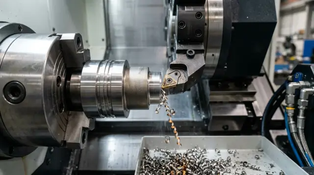
First check coolant delivery. The jet must hit the cutting zone, not wash the toolholder body or miss to the side. If coolant doesn’t reach the edge, chips break worse, temperature rises and scratches or burn marks appear.
Then check the coolant itself. The same program can give different results if concentration has drifted, the fluid is foaming, or the tank has collected sludge. This is often noticed late, after a run with unstable size.
What to check regularly:
- working concentration of the emulsion, not by eye;
- cleanliness of the chuck, jaws, stops and datum areas;
- filters and coolant channels if flow is weak;
- datum surfaces before each new setup.
Fine chips cause frequent problems. They pack into the chuck, settle on stops and stay on datums. A single thin chip can tilt a blank enough to move size by several hundredths.
A good rule is simple: don’t wait until the end of the shift; clean the units in short cycles. After a batch the operator blows out and wipes the chuck, checks nozzles, verifies coolant pressure and cleans contact points. It takes minutes but often saves an entire run.
On CNC lathes this discipline pays off quickly. Scrap falls not because of one big change but because of a set of small daily actions.
How to monitor tool wear
On stainless and titanium the tool often fails before the operator sees clear scrap on parts. Waiting until the end of a shift can cost you size drift, burrs or ruined surfaces across a batch.
Link inspections to the number of parts rather than time. For example, inspect the insert after the first 10–15 parts, then every 5 parts; once the regime is clear inspect every 20–30. This shows real tool life for your operation faster than relying on a section average.
Look for more than just chips. With difficult materials quieter signs matter: the wear land broadens, material sticks to the edge, cutting noise gets harsher, and chips change color and shape.
When inspecting check:
- the width of the wear land on the flank;
- material buildup on the cutting edge;
- increased noise during cutting;
- spindle and feed loads if the machine displays them;
- changes in chip color and shape.
If the cutting sound gets harsher and chips become torn, don’t wait for size drift. On titanium this usually means the edge is already hotter than normal. On stainless a buildup first causes unstable roughness, then size defects.
It’s better to replace the insert a bit early than after a part goes out of tolerance. It may seem like extra cost, but an early change is almost always cheaper than scrapping a batch. Once you see steady wear growth and early signs of unstable cutting, fit a fresh insert and record the result.
You don’t need a complex system. Keep a short card per operation: material, tool, regime, coolant, number of parts to change and reason. A couple of shifts will show where the tool genuinely reaches life and where you’re risking scrap.
How to launch a new part
Don’t start a full run of a new stainless or titanium part immediately. Begin with a short trial batch. Usually 3–5 pieces are enough to see how size, surface and the tool behave.
The first part matters, but don’t base the whole regime on it. After roughing and finishing let the part cool. Stainless and titanium can give a false size when measured hot: it may look fine on the machine and then shift after 15 minutes.
A practical order:
- Run 2–3 parts at cautious settings without trying to max out speed or feed.
- Check the first part’s basic dimensions: diameters, lengths, fits, runout and surface condition.
- After cooling repeat the finish measurement and compare.
- Adjust parameters slightly on the second and third parts, one parameter at a time.
- When size is stable record the working scheme for the series.
Don’t change everything at once. If you increase feed, tweak offsets and replace the insert together, you won’t know what produced the result. This mistake is common on difficult materials.
Keep a short setup card: blank material, tool grade, overhang, regimes, correction number and measurement results for the first three parts. These notes save time on repeat orders and reduce the chance that the next shift starts tuning from scratch.
If your shop runs similar parts in series, this discipline pays off fast. You spend an extra 20–30 minutes at start but the run goes steadier and scrap doesn’t appear at the end of the batch.
Common mistakes
Scrap usually rises not from one big cause but from a set of familiar mistakes. Each seems small, but together they cause size drift, surface scratches and unstable repeatability.
The first simple mistake: the operator raises speed to save a minute on cycle time. On easy materials this sometimes works, but on stainless and titanium it quickly causes edge overheating, buildup, vibration and geometry drift. The shop saves a minute per part and then loses hours on sorting and refitting.
The second common issue is keeping an insert too long. The logic is clear: if the tool still cuts, stretch the changeover. But wear on these materials rarely increases smoothly. It can look fine until the edge suddenly fails and scrap comes in a series. It’s much cheaper to change tools on a clear limit.
Third mistake: measuring hot parts as finished. That makes size "float" and the team starts adjusting offsets without a real reason. With tight tolerances let parts cool to a stable state or set a single measurement rule for all shifts.
There are also very down-to-earth problems. Chips in the jaws, on datums and in fixtures change the part clamping by fractions of a millimeter. For titanium and stainless that’s enough to cause runout, taper or marks from reclamping.
Another trap is changing the tool and parameters at the same time. After that no one knows what helped or harmed. If you fitted a new insert keep the old regimes. If you change speed or feed, leave other settings untouched for a few parts.
Pre-run checklist
Spend 10–15 minutes on checks before a run — it’s better than unpacking a box of scrap later. On stainless and titanium small things turn into big problems quickly.
Do the check every time, even for familiar parts. The same program can behave differently if shop temperature changed, coolant concentration dropped or the tool is near the end of life.
Five items usually suffice before a run:
- the machine is warmed up and spindle and axes are at operating conditions;
- coolant is OK: level, concentration, cleanliness and jet aimed at the cutting zone;
- the tool is set per the card with correct overhang, position and remaining life;
- the first part is measured at the points where drift, taper or roughness appeared before;
- operator and inspection share the same standard for surface quality.
Most problems come from a chain of small deviations: the machine wasn’t warmed up, the tool was kept “until the end of the shift”, the first part was measured on two dimensions — and the run became unstable. Later they look for material issues when the cause was preparation.
Fix this checklist at the machine and tick items before start. In shops that often run stainless and titanium, this habit helps more than trying to correct regimes during the run.
Shop example
A lathe cell started a run of stainless bushings. Early parts met size, but the surface was torn: shiny patches, matte bands and build-up on the cutting edge.
They first suspected the blank, but the cause was closer. Inspection found material sticking on the insert — common with stainless when the cutting zone is overheating and cooling is weak. They also checked coolant and found the nozzle partly clogged so the jet missed the cutting point.
They fixed things in order. First they reduced cutting speed slightly to lower heat. Then they replaced the insert because the buildup already damaged the edge. Finally they cleaned the coolant line and aimed the jet directly at the cutting zone.
After three parts the situation stabilized. Size stopped wandering, roughness became consistent and the new insert didn’t pick up buildup as quickly. That’s a good sign: the defect disappeared after clear actions, not by chance.
The same approach is even more important for titanium. It reacts stronger to overheating and has less margin for error. If cutting noise becomes harsh, deposits appear on the edge or the surface quickly loses finish, stop immediately. A small speed reduction, a fresh insert and clean coolant often catch the problem before size goes out of tolerance.
What to lock in after early improvements
Early gains are easy to lose. Put good settings into short shop rules so they don’t stay only in the master’s head. Otherwise a tool change, a new bar batch or another operator will bring back old issues.
Create a simple regime card by material and operation. No thick manual — one page for stainless, one for titanium and notes by part type. Usually list the blank grade, tool and insert, working regimes and the point when the tool starts to harm surface or size.
Next, stop changing inserts "by eye." Tie changes to part counts. If an insert reliably holds for 40 parts on stainless, change it earlier, for example at 34–36. For titanium be even more conservative — wear often accelerates suddenly.
Weekly, review scrap facts without long meetings. Open the log and see: which machine showed defects, after how many parts, which tool, which program and which shift. This quickly reveals repeating causes. Often the culprit isn’t the material but the same small issue: a dirty chuck, late insert change or an old offset.
If the process stays unstable, honestly check the machine. Worn mechanics, weak coolant pump, heating or an unstable spindle can prevent holding size even with correct regimes and discipline.
At that point talk with equipment and service suppliers. For enterprises in Kazakhstan a partner can be EAST CNC: the company works with CNC lathes for metalworking and helps with selection, commissioning and service. The conversation is useful not to replace equipment immediately but to understand where current machine limits are and where to improve the process.
Finally, keep three weekly numbers: scrap rate, tool life in parts and the number of stops for adjustments. If any of these rise, you’ll notice before a run starts to lose money.
FAQ
Why do the first parts pass inspection, and scrap appears later?
This happens because of heat and tool wear. The first parts are fine, but then buildup on the insert or a small chip appears and surface finish and size start to drift.
What should I check first besides size?
Look at the surface finish, burrs, the chips and the sound of cutting first. These signs usually change before the part goes out of tolerance.
Can I measure a part immediately after machining?
No. Let the part cool down and then recheck. Stainless steel and titanium can show one size hot and a different one after a few minutes.
Which cutting parameters are best to start with on stainless steel and titanium?
Start with moderate spindle speed and a steady feed. Separate roughing and finishing passes so you don’t overheat the tool and can control surface quality.
Why does too low a feed also damage the part?
Too low a feed often turns cutting into rubbing. The tool stops cutting cleanly, the surface work-hardens, temperature rises, and defects follow faster.
How do I know it’s time to change the insert?
Don’t wait for a visible chip. If wear land grows, material starts to stick to the edge, the cutting sound gets harsher, or chips change color or shape, replace the insert before the batch goes bad.
What to do if chips are winding onto the part?
First check coolant flow, feed and cutting speed, and chip evacuation. If chips wrap onto the part they will scratch the surface and increase local heat.
Why does coolant feed affect scrap so much?
Because the coolant jet must hit the cutting zone. If it misses the edge, the metal heats more, chips don’t break well, and scratches and burn marks appear.
Can one setup cover both roughing and finishing passes?
Usually not. Roughing removes the bulk of the stock and aims for stable material removal; finishing focuses on size and surface. One setting for both often creates excess heat and unstable results.
What should I check before starting a production run?
Check that the machine is warmed up, the tool condition, cleanliness of the jaws and fixtures, coolant concentration and pressure, and measure the first part in the areas that previously showed drift. These checks often save a whole batch.