New Part Launch Folder: What to Keep in One Place
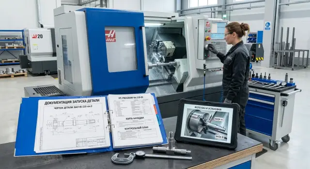
A new part launch folder helps keep the drawing, CNC program, setup sheet, inspection plan, and base photos in one place without confusion or downtime.
Why production slows down without one folder
When a new part is launched, downtime often starts not at the machine, but with paperwork. One department is waiting for the drawing, another for the program, quality is looking for the latest inspection plan, and the base photos are somewhere in a chat. In the end, people spend their time not on setup, but on searching.
The most common problem is simple: no one knows which drawing is the working one. In the shared folder, there are several PDFs with similar names, another version is in email, and the technologist only remembers that "the chamfer was tweaked a bit there." On the shop floor, details like that quickly turn into an extra hour of downtime.
The same goes for the CNC program. While the programmer keeps the file only on their own computer, everything seems fine. But once they switch to another project, go on sick leave, or simply do not reply right away, the launch stalls. The setter starts working from memory, and for a new part that is a poor foundation.
Quality can also get off track if it uses old documents. The inspector opens the previous inspection plan, checks the wrong dimensions, or misses a new tolerance. The part is already made, time is gone, and then it turns out they checked an outdated version.
Base photos get lost just as often. They are taken on a phone, sent to a chat, and a week later nobody is sure where the first setup was or how the blank was oriented. For a simple part, that can still be reconstructed. For a series with repeat setups, it is much harder.
It usually looks the same: the setter looks for the latest drawing, the programmer sends the CNC program from a personal folder, quality opens an old template, base photos are searched for in a messenger app, and the first launch gets pushed back by half a shift.
On a CNC lathe shop floor, this kind of mismatch quickly hits deadlines. The problem is not the people and not memory. The launch documents simply live in different places. When everything is gathered in one folder, the launch no longer depends on one person and goes more smoothly.
What should go in the folder
A new part launch folder is not for keeping the server tidy. It is there so the technologist, setter, operator, and inspector all work from the same set of files. If everyone has their own source, the shop starts losing time on the very first setup.
The minimum set is straightforward. The folder should contain the documents you need to take a new part and get it to the first good piece without extra calls.
Required set
- Drawing with the part number and revision.
- CNC program with a clear file name.
- CNC setup sheet.
- Part inspection plan.
- Photos of the bases, clamping, and first good part.
It is best to keep only the approved version of the drawing. If engineering changes a dimension, radius, or tolerance, the old copy in the working folder breaks the whole process. Only the revision the shop is actually using should remain in the folder.
The same rule applies to the CNC program. If three almost identical files with unclear names are sitting side by side, the operator starts opening them one by one and guessing. On paper it seems minor, but in practice 20-30 minutes can disappear before the first part.
The setup sheet and inspection plan cover different tasks. The first helps you quickly build the machine and tooling. The second keeps you from missing the dimension that tends to drift first. For a production part, that is especially important: the first launch is sometimes saved by experience, but repeatability depends on clear documents.
Photos should not be treated as a formality either. One shot of the setup and one shot of the correct clamping are often more useful than a long comment. A photo of the first good part helps quickly compare appearance, marking, and problem areas on the next launch.
How to name files and versions
If the folder contains files like "new drawing", "final program", and "latest setup sheet", the launch almost always slows down. People waste time guessing. One clear naming format solves this better than any verbal agreement.
It helps to use one rule for all files. The same parts should appear in the same order in every name: part number, document type, revision, and date. Then it is immediately clear what you are looking at and which version is current.
A template like this works well:
- 15427_drawing_R02_2026-04-13
- 15427_CNC-program_op10_R02_2026-04-13
- 15427_setup-sheet_R02_2026-04-13
- 15427_inspection-plan_R02_2026-04-13
- 15427_base-photos_R02_2026-04-13
This format is convenient for a simple reason: files sort by part number and do not get mixed up. The date is best written as YYYY-MM-DD. That way the list stays in order, and the latest revision is visible at a glance.
Words like "final", "new", and "latest" are better left out completely. A week later, "latest" is no longer the latest, and "final" often turns out to be a draft after a tool or setup change. Revision numbers like R01, R02, R03 are more honest and leave no room for arguments.
How to store working and old versions
Keep working files separate and move old versions to an archive. Do not mix them in the same folder. If everything is left together, someone will inevitably open an old CNC program and start the wrong operation.
A simple rule works best: the working folder contains only what can be taken to the machine today. Anything replaced goes into an archive or old folder with the same naming structure.
Before releasing it to production, check the part number in every document. A one-digit error happens more often than you would think. The drawing may be for part 15427, while the setup sheet is for 15472, especially if the parts look similar and the series runs one after another.
If several launches are running at the same time on different machines, a single naming format saves a lot of small minutes every day. And that is exactly what a calm launch without extra calls is made of.
How to prepare the drawing, CNC program, and setup sheet
If the operator opens the drawing and cannot see what to set the part from, the launch slows down immediately. On the working drawing, it is best to mark separately the dimensions needed specifically for setup and first inspection. These are the bases, distances to stops, fits, and tolerances on surfaces that cannot later be "caught" with one correction.
Along with the geometry, include the starting blank data. The material, blank size, and allowance should be written so the person at the machine does not have to rely on memory or search an old order. For example: 45 steel, 42 mm bar, blank length 128 mm, allowance 1.5 mm on diameter, 2 mm on the end face. One line like that often saves more time than long explanations.
What to write in the CNC program and setup sheet
The CNC program should be firmly tied to the part and the drawing revision. In the comment at the start of the program, note the part designation, operation number, revision, blank, and the author of the latest change. If engineering changes the dimension and the program still shows the old revision, one folder will no longer save the day.
The setup sheet should contain the minimum needed to confidently set up the first part: a tool list with position numbers, operations, offsets, part zero, and the setup diagram. You do not need a pretty drawing taking up half a page. A clear sketch is enough, showing tool overhang length, stop point, clamping location, and where Z0 and X0 are taken from.
For a CNC lathe, this can be very short: "Z0 at the front face of the blank, clamp 28 mm, stop against the rear face." For a milling operation, show which zero is set in G54 and which surface it is picked from.
A good setup sheet answers one question: can another setter launch the part without calling the program author? If not, the document is still rough.
How to build the inspection plan and base photos
The inspection plan is needed in the first hours of the launch. It helps quickly understand what to measure after the first part, what to measure with, and how often to repeat the check. In the folder, it should sit next to the drawing, CNC program, and setup sheet, not in someone’s personal folder.
First, choose the dimensions that most often drift at startup. These are usually base diameters, lengths, fits, runout, threads, and dimensions after part repositioning. There is no need to move the whole drawing onto the first page. For launch, 5-10 dimensions are more important — the ones that quickly show whether the process is in tolerance or not.
For each dimension, write not only the nominal value and tolerance, but also the measuring tool. One operator will use a caliper, another a micrometer, and the results will already differ. So it is better to write it directly: 25-50 micrometer, bore gauge, dial indicator, thread gauge, height gauge. If the dimension is measured in a fixture, that should be noted too.
Choose the inspection frequency based on the actual work. For the first parts, it may be 1st, 3rd, and 5th piece. For a series, every 10 or 20 parts. Sometimes it is more convenient to count by time, for example once every 30 minutes or once an hour. After a tool insert change, re-setup, or machine stop, the inspection should also be repeated separately.
The same dimension does not always need the same inspection frequency. If the diameter is stable, it can be checked less often. If a size depends heavily on tool wear, check it more frequently.
Base photos are not taken just to check a box. From the pictures, the operator should immediately understand which surface the part rests on, what is being clamped, and how it is oriented. Usually a few shots are enough: a general view of the setup, a close-up of the base surfaces, the stop position, and the direction of part installation. The photos should be sharp and free of clutter.
It is better to label the pictures clearly. Instead of "Photo 1", it is more useful to write: "Base A on the jaws", "Stop against the face", "Orientation with the hole up", "Runout check after clamping." If the part can be set incorrectly in two ways, show the correct and incorrect options separately.
A good inspection plan and clear base photos save time on the very first shift. The operator spends fewer minutes guessing, and the supervisor can more quickly understand where the mistake is — in the setup, the tool, or the program itself.
How to build the folder step by step
The folder should be put together before the first problem, not after it. It is better to create a template before the new part even reaches the shop floor. Then the operator, setter, and inspector open one place and immediately see what they are working with.
The easiest way is to create one main folder for the part and keep the same structure inside it for every launch. Too many nested folders do not help. On the contrary, people start storing files on their desktop or in a messenger app.
- First, create a folder template. Simple sections are enough: drawing, blank, CNC program, setup sheet, inspection, and photos.
- Before the trial run, put the drawing and blank data into the folder: material, size, allowance, and, if needed, weight.
- After the first trial, add the working CNC program and the CNC setup sheet. Do not wait for the perfect version. Save the one that actually got the part into production.
- Right after setup, save photos of the installation and bases. Usually two or three shots are enough: a general view, a close-up of the base setup, and one important moment related to the tool or clamping.
- On the same day, enter the first measurements and assign one person to update the folder and track the versions.
In practice, it looks simple. In the morning, the technologist adds the drawing and blank data; during the day, the setter adds the CNC program and setup sheet; in the evening, the inspector attaches the first measurements and base photos. The next day, the shift does not start with questions.
If a folder has no owner, it quickly falls apart. One employee keeps the new CNC program, another edits the setup sheet on their own computer, and a third looks for photos on a phone. That is why it is better to assign responsibility right away. Most often, this is the technologist or setter running the launch.
For production work, this structure does not bring abstract benefits — it saves real minutes on every repeat start. And if the part comes back in a month or moves to another shift, the folder answers most questions without extra searching.
Example for a simple production part
A good example is a regular bushing made from bar stock. The part is simple: outer diameter, inner hole, length, and two chamfers. On parts like this, it is easiest to see why one well-built folder saves time in the very first shift.
The folder for this bushing does not contain everything under the sun, only what is needed to start without guessing: the drawing with dimensions marked for first inspection, the CNC program for the specific machine, the setup sheet with tools and overhangs, the inspection plan for the first checks, and photos of the bases from the first setup.
The operator opens the photos and immediately sees how to clamp the bar, how far to extend the material, and where the zero point is. They do not need to call the setter and ask which side the part should face. One clear photo often removes more questions than half a page of text.
The setter takes the setup sheet and works from the prepared list. For example, it lists a turning tool, a drill, a boring tool, and a parting tool, with position numbers and the needed offsets next to them. If the tools are already assembled from that sheet, the setup goes smoothly, without fuss.
Quality does not waste time on the whole drawing. The plan marks only three dimensions for the first launch: the outer diameter, the bushing length, and the hole diameter. That is enough to quickly tell whether the first part and the small adjustment are on size.
This kind of set also helps the next shift. If the first good part was made in the evening, the night shift does not start over from someone else’s words. People open the same folder, see the same photos, the same tool list, and the same inspection order.
The effect is especially noticeable for simple production parts. A bushing is not complicated in itself, but even it can fail on small things: the base was mixed up, the wrong tool was used, the wrong dimension was checked. One tidy folder removes these errors before the first chip is cut.
Mistakes that break the launch
Most often, the launch is not stopped by the machine, but by mess in the documents. When the drawing is in email, the CNC program is in a chat, the base photos are on the setter’s phone, and the setup sheet is on someone else’s computer, every small issue turns into downtime.
First, the shift loses 15 minutes searching for files. Then the operator takes the wrong program version, the setter installs tools from an old sheet, and quality measures a dimension that was already changed in the latest drawing. It is a common mistake, but the price is unpleasant: scrap, delayed deadlines, and extra changeovers.
One of the most common failures is when the CNC program has already been changed, but the setup sheet has not. The tool overhang in the program is one value, and in the setup sheet it is another. On paper, one base is shown, while the photo shows another. People start checking everything manually and arguing about which file is correct. If the launch depends on one technologist remembering everything, the process is already fragile.
Photos are also often taken just to have them. There is a picture, but little value: no label, the side of the part is unclear, it is not obvious which setup is the first and which is the second. A week later, even the person who took the photo may not remember what they meant to show. A proper photo should answer two questions: how the part is positioned and what it is located from.
Another mistake is keeping only PDFs. PDFs are easy to open, but that is not enough for production. If a dimension, tool path, or setup-sheet text needs to be changed quickly, the team has to search again for whoever still has the working version. The folder should contain both approved files and editable source files.
In short, launches break for five reasons: documents are scattered, versions do not match, photos are unlabeled, the folder contains only PDFs, and nobody updates anything after the first batch.
The last point is often the most painful. The first batch is done, and during production someone found a more convenient base, changed the feed, or adjusted the inspection. If nobody enters that into the folder, the second launch will repeat the old data. That is why one responsible person is needed to collect the changes after the first batch, save a new version, and briefly note what changed.
Quick check before the first launch
Before the first run, open all the files from one folder and do a quick check. It takes 10-15 minutes. But after that, you do not have to stop the machine because of someone else’s typo or an old program version.
It is worth checking not the general order in the folder, but the match between specific data in the drawing, CNC program, setup, and inspection plan.
- Check the part number in all files.
- Verify the drawing revision and the CNC program revision.
- Compare the setup sheet with the actual tools at the machine.
- See whether the inspection plan includes the first critical dimensions.
- Make sure the base photos clearly show the setup, stop, and part orientation.
A fault usually hides in a small detail. On a CNC lathe, it often looks like this: the setup sheet shows the tool in position T0303, but in the turret it is in T0404. The operator notices this only at the machine, loses time, and starts checking everything again by hand.
Another common miss is a good-looking inspection plan that does not include the first critical dimension after the roughing pass. As a result, the first part is measured too late. If the size has already drifted, the batch has to be corrected, and sometimes the blanks must be scrapped.
A simple check works best: any setter should be able to open the folder and understand the launch without calling the technologist. If questions come up on the very first look, it is better to fix the folder before the start, not after the first defective part.
What to do next
After the first batch, the folder should not be considered finished forever. It is the trial run that shows where the operator needed more explanation, where the setter had to change an offset manually, and where quality spent an extra 15 minutes because a dimension in the plan was unclear.
That is why it helps to do a short review right after the first series. It is better to do it the same day or in the next shift, while people still remember what went wrong and what had to be adjusted on the spot.
You do not need to update everything, only what affects repeat launches: changes to the CNC program after test cuts, actual tool and offset corrections, clarifications in the setup sheet, new base photos, and notes in the inspection plan if a check was added or the measurement order changed.
There is no need to delete the source files. It is better to keep the original and the actual working version with a clear note. Then the next person can see what was planned first and what actually worked on the machine. This is especially useful if the part comes back a month later and another shift handles the launch.
After the update, leave one working set. If the folder contains three CNC programs, two setup sheets, and old photos without labels, people will start guessing again. And guessing on the shop floor usually ends in downtime or scrap.
If the launch is being prepared for a CNC lathe or a machining center, the documents should be tied to the real way the equipment works from the start. Practical experience from the supplier also helps here. At EAST CNC, the company ТОО Метиз, the blog includes equipment reviews and metalworking tips, and the company itself provides supply, startup, and service for machine tools in Kazakhstan and other CIS countries.
A good folder does not depend on the memory of one person. It shows how to launch the part today, not how it was once done by word of mouth.