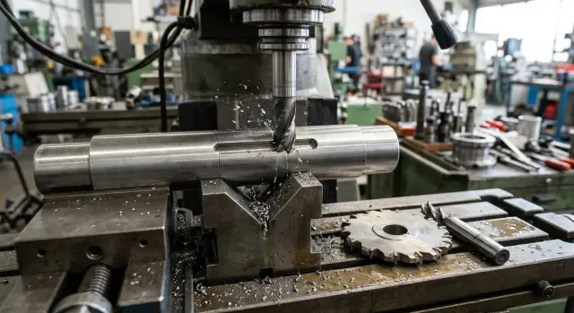
Milling a Keyway Slot in a Shaft: Disc or End Mill
Milling a keyway slot in a shaft requires a precise tool choice. Let’s compare a disc cutter and an end mill in terms of runout, straightness, and setup.
Why the choice of cutter changes the result
The same slot on the drawing does not always produce the same slot on the part. In practice, width, straightness, and wall condition depend not only on the tool size, but also on how it cuts. That is why the choice between a disc cutter and an end mill affects the result more than the catalog description suggests.
A disc cutter usually holds the width better. Its thickness already defines the size, and the cut follows the profile of the tool itself. If the arbor is sound and the seating is clean, the slot is less likely to "wander" in width. An end mill is easier to use and simpler in tooling, but it reacts more strongly to stick-out, wear, feed rate, and clamping condition. On paper the diameter is the same, but in metal the slot may come out slightly wider or leave walls that are not quite even.
Runout shows up especially quickly in a keyway slot. Even a small deviation with an end mill creates uneven material removal: one wall comes out cleaner, while the other shows waviness or a noticeable mark. A disc cutter is also sensitive to runout, but it is easier to track through the arbor, seating, and side drift. If the setup is done carefully, the walls more often come out straighter.
A lot of problems also appear after a repeated setup. Today the cutter was installed with one stick-out, tomorrow with another. The shaft sits in the clamp a little differently, zero is found again, and the slot no longer matches the previous part. This happens more often with an end mill because stick-out and overall rigidity have a bigger impact on the result. A disc cutter on an arbor is usually easier to return to the previous position if the setup scheme has already been worked out.
That said, the cutter itself is not always the main issue. Very often the size is thrown off by the setup: the shaft is poorly supported and shifts under load, the workpiece is clamped at an angle, the part axis does not match the base, dirt remains in the collet or on the arbor, or the holder or machine has play. If the shaft is long and slender, even a good tool will not prevent drift. That is why the cutter is always chosen together with the setup method, not separately from it.
Where a disc cutter gives more control
A disc cutter usually wins where the slot has to be the same along its full length, not just "within tolerance" at one point. This is especially noticeable on long parts and on batches of identical shafts.
The main advantage is simple: the width is defined by the tool thickness. If the cutter is in good condition, the spindle does not run out, and the cutting conditions are not too heavy, the slot keeps the same size from entry to exit. With an end mill, the width depends more strongly on lateral drift. Even slight wear or small runout can add extra thousandths, and not always evenly along the length.
Stick-out also plays a major role. A disc cutter is mounted on an arbor, and the cutting section sits close to the support. The tool bends less under load, the cut is steadier, and the wall comes out straighter. An end mill often has more stick-out, especially if it needs to reach the shaft center or clear a clamp. The longer the stick-out, the easier it is for the tool to move sideways.
On a short slot, the difference may be almost invisible. On a long one, it shows immediately. The first few millimeters of cut often look good with both options, but farther along the end mill is more likely to start pulling the slot off line: the wall becomes wavy, the width shifts slightly, and the axis moves by fractions of a millimeter. A disc cutter is less prone to this kind of movement in the cut, so it usually holds a straight line better.
This is also noticeable during repeat setups. When the operator returns to the same part after a tool change, it is easier to get the same result with a disc cutter. The thickness already defines the width, and all that remains is to return the center and depth accurately. With an end mill, the spread between parts is usually larger because the size also depends on the actual diameter, edge condition, and runout after installation.
On a batch of 30–40 shafts, the difference becomes very practical. If the slot is long, the tolerance is tight, and there is no time for repeated trial cuts, a disc cutter usually gives more predictable geometry.
When an end mill is still more convenient
An end mill has its own strong advantage: simplicity. If the shaft is already clamped and access to the cutting area is available from above or from the side, the operator can often just install a standard end mill and start work without a separate arbor for a disc cutter.
This option is a good fit for a one-off part, repair work, or a small trial batch. When only one slot is needed, the setup for a disc cutter sometimes takes longer than the machining itself.
An end mill is especially handy where space is tight: the slot is near a shoulder, chuck, or another element that a disc cutter cannot easily reach. It also helps when the part must be machined in one setup without moving it to another fixture. If the machine already has the right holder, changing the tool really does take only minutes.
But convenience ends quickly as stick-out grows. The farther the cutting part sits from the collet or chuck, the easier it is for the cutter to drift under load. At first it looks minor, but on the part it shows up quickly: the bottom of the slot comes out uneven, the wall starts to "float," and straightness is lost toward the end of the pass.
On a long shaft, this is especially easy to see. If the part cannot be moved closer to the support, the operator often installs a longer cutter just to reach the cutting zone. The slot is produced, but by the end of the pass the width and position may shift by several hundredths. For a one-off part, that is sometimes acceptable. For a series, it is already a risk.
Repeated setup is also harder for an end mill. A disc cutter keeps the width by its body, while an end mill depends more heavily on the exact zero, stick-out, edge condition, and how the shaft is clamped the second time. So between batches, or even between two identical setups, the result varies more noticeably.
If the job is simple, the part is one-off, and access is awkward, an end mill is perfectly reasonable. If you need the same slot across a series of shafts, its convenience quickly gives way to the need for stable geometry.
What to check before the first pass
Errors in a keyway slot often appear even before cutting starts. The tool is installed at an angle, the arbor has play, the shaft is clamped with a tilt, and the first pass already creates drift. Accuracy here depends not only on the cutter choice, but also on the whole chain: spindle, arbor or collet, tool, and part clamping.
Start by checking the tool seating. For a disc cutter, that means clean seating surfaces, the condition of the arbor, and the clamping rings. For an end mill, check the collet, chuck, and shank. Even a small chip or burr can create tilt and then noticeable runout.
Keep stick-out to a minimum. The farther the cutter is from the support, the easier it is to pull off line under load. With a disc cutter, it helps to place the support as close to the tool as possible. With an end mill, leave only the stick-out needed for the depth. An extra 10–15 mm often hurts straightness more than expected.
Before the test cut, check runout with an indicator. Check not only the outer diameter of the cutter, but also the arbor or shank to see where the error begins. If the readings change after reinstalling the tool, the cause is usually the seating, dirt, or clamping wear. If the readings stay stable, look at the spindle and the tool itself.
It is useful to check four units right away: the spindle, the arbor or chuck, the cutter, and the part clamping. Operators often replace the tool when the real problem is in the V-block, centers, or vise. If the shaft sits unevenly or flexes slightly under clamping force, the slot will drift even with a good tool.
Another common mistake is mixing new and worn tools in the same batch. An old disc cutter cuts differently from a new one, even with the same marking. After regrinding, the behavior of an end mill also changes noticeably: the load increases, the actual cutting width changes, and the center setting shifts. When the tool changes, check runout, zero, and the test part again.
These checks take only a few minutes, but they save hours of rework later. First remove play, reduce stick-out, and check seating. Then cut.
How to set up the operation step by step
Setup often affects the result more than the difference between two similar cutters. If the base is shifted even slightly, the slot drifts in width or line, and that quickly shows up during assembly.
First choose a cutter for the finished slot size, not for a size that "almost fits." For a disc cutter, the thickness should immediately give the required width. For an end mill, decide in advance whether you will reach size in one pass or leave a small allowance for finishing.
Then set up the shaft carefully. V-blocks, stops, and clamps should hold the part the same way every time it is installed. If the shaft sits unstably, a precise cutter will not fix that.
Before a batch, make a test pass on a rough part or on a blank of the same diameter and material. There is no need to go straight to full depth. It is often wiser to remove a little, inspect the cut, and only then move to the final size.
After the test pass, check the width along the full length, the depth from the chosen base, drift toward the end of the pass, vibration marks on the walls, and repeatability after reinstalling the part. If the slot comes out wider than allowed, first look at tool runout and mounting. If the size changes along the length, the shaft base, feed, or weak clamping is usually the cause.
When the test part is in size, record not only the coordinates but also the setup method itself. Write down the tool stick-out, part zero, depth, stop position, and clamping order. A simple setup record helps a lot when the batch returns a week or a month later.
This matters especially on a batch. The operator does not have to search for the base again or chase the size on the second or third part. For a disc cutter, this approach usually works even better because, after a successful setup, its position is easier to reproduce without extra corrections.
Mistakes that most often ruin the slot
Defects in a keyway slot often start not with the cutter, but with small decisions made before cutting. The width may be within tolerance, yet the slot is still problematic: it drifts off line, gives different depth along the length, or starts binding the key during assembly.
The first typical mistake when using an end mill is too much stick-out. The longer the tool, the easier it is to move off line under load. On a short slot this is sometimes almost invisible, but on a long shaft it shows up quickly: the entry is straight, and the middle already starts to "float."
The second mistake is not checking runout after changing the arbor, collet, or cutter itself. The tool is clamped, everything looks fine visually, and the machine is started right away. Later there is a wave on the wall and a width that changes from part to part. A few hundredths of runout is already a lot for a narrow slot.
The third problem is changing the base between batches. The first ten shafts were referenced from one stop, and the next ten after a reset from another. Formally the size from the end face may stay the same, but the slot position relative to the journal or seat shifts. Yesterday everything assembled, today the key is a tight fit.
Feed and depth of cut are also often set poorly. If all the allowance is removed in one pass without leaving anything for finishing, the tool takes on extra load. The end mill starts to deflect, while the disc cutter may leave a rough side surface if the feed is too high. One roughing pass and one finishing pass almost always give a calmer result.
And one more mistake: the slot is judged only by width. That is not enough. Straightness, even depth, and wall condition also need to be checked. If the slot starts to wander, the cause is usually found here, not in the shaft material.
An example with a batch of shafts
In a batch, the difference between cutters becomes very clear. On a single part, almost any setup can give an acceptable result. On a run of 20 or 50 pieces, you can see how well the tool keeps the slot consistent.
Imagine a 40 mm shaft with a standard keyway slot. On the first shift, the operator makes a test part with an end mill, sets the width and depth, gets within tolerance, and starts the batch. The first part passes smoothly. The second and third also look fine.
Problems appear a little later. On the fifth part, the slot is not badly off yet, but the walls are no longer as even. Measurement shows that the width is sitting at the edge of tolerance, and straightness is worse than on the first part. The operator adjusts the position again, even though at the start the setup already seemed finished.
The pattern usually repeats: the slot is cleaner at the entry than at the exit; one wall picks up more evidence of runout; after a repeated pass, the size changes more than expected; and after a machine stop, almost everything has to be checked again. The reason is simple: in this kind of work, an end mill reacts more strongly to side load and even slight runout.
When the same batch is switched to a disc cutter, the work usually becomes calmer. The walls come out straighter along the full length because the tool is less likely to drift sideways. The width is easier to keep consistent from part to part, and the mark on the side walls looks more even.
The difference becomes even more obvious on the next shift. If the operator returns to the same batch the next day, the repeated setup with a disc cutter takes less time. The tool thickness immediately provides a clear width reference, and the position is easier to bring back to the previous settings. With an end mill, an extra trial pass is more often needed because even a small axial shift or a different clamp changes the result.
A batch usually puts everything in the right place better than any theory. If you need one slot, an end mill may be completely fine. If you need ten identical shafts in a row, a disc cutter is often the calmer choice.
Short checklist before a batch
Before starting a batch, it is worth quickly checking a few things:
- slot width at the start, middle, and end
- tool runout before the first cut
- the same base on all parts
- cutter stick-out and clamping rigidity
- not only the size, but also the slot line along its length
One successful test part does not guarantee anything yet. A batch usually fails on small details: the cutter has slight runout, the shaft shifted in the base, and no one wrote down the parameters after the first setup. It is much easier to stop after the first part and correct the setup than to notice drift on the tenth blank and rework the whole batch.
What to do next
If you have not yet decided which tool to keep in production, compare both options on the same blank. Take a shaft of the same material, with the same stick-out and the same clamping. Run one slot with a disc cutter and the other with an end mill, without adjusting things "by eye" between attempts.
Look at more than width and depth. Often a slot passes gauge, but along the length it drifts by several hundredths, and that already shows up during assembly. So measure width and depth at the start, middle, and end, record the runout before cutting, and note how much time was needed for the repeated setup after changing the cutter.
Many people underestimate the last point. On one part, a difference of 10–15 minutes is barely noticeable. On a batch of shafts, that is already hours of work, extra checks, and a risk that another operator will set the tool slightly differently.
If the task is no longer about one operation, but about choosing equipment for a stable production run, it is better to discuss it with the people who are responsible for both startup and service. EAST CNC helps with equipment selection, commissioning, and maintenance in Kazakhstan, and the east-cnc.kz blog publishes equipment reviews and practical metalworking tips. For this kind of discussion, it helps to show a test part, the slot tolerances, and the time needed for repeated setup right away.
FAQ
When is a disc milling cutter better than an end mill?
A disc milling cutter is usually chosen for long keyways, tight tolerances, and batches of identical shafts. It typically holds the width and line more evenly along the full length because the cutter thickness defines the size and the cutting edge sits closer to the support.
When does an end mill work well?
An end mill is convenient for a single part, repair work, and tight access when you do not want to set up a separate arbor. This option works well if the slot is short, the tolerance is not too tight, and the part can be machined in one setup.
Why does a slot cut with an end mill often come out wider?
The size is usually thrown off by runout, excessive stick-out, worn edges, and weak clamping of the part. The drawing may show one diameter, but during cutting the tool is pulled sideways, and the slot ends up wider or develops a wave on one wall.
How much does tool runout matter?
Even a few hundredths can already ruin a narrow slot. Runout quickly creates uneven cutting on the walls, marks on the side surfaces, and variation from part to part, so it is better to check it with a dial indicator before the first pass, not after scrap appears.
What tool stick-out should be considered safe?
Keep the stick-out as small as possible while still allowing access and depth. An extra 10–15 mm often noticeably worsens straightness, especially on a long shaft, so the support and tool should be brought as close to the cutting zone as possible.
What should be checked before the first pass?
Before cutting, check the seating cleanliness, the condition of the arbor or collet, tool runout, clamping rigidity, and shaft support. If the shaft sits skewed or flexes under clamping force, even a good tool will not keep the slot on line.
Is it worth separating roughing and finishing passes?
Usually yes, especially for a batch and for a long slot. A roughing pass removes the main load, and a finishing pass helps bring the width, depth, and walls into shape more calmly and with less drift.
How should a test part be checked properly?
Measure the width and depth at the start, middle, and end, not just at one point. Also look at straightness, vibration marks on the walls, and repeatability after the part is reset.
How can you tell the problem is not the cutter, but the setup?
When the size changes after reclamping, one wall looks cleaner than the other, or the slot drifts toward the end of the pass, first look for an error in the base, clamping, and shaft support. The tool is often replaced too early, even though the real problem is usually in the V-block, centers, or chuck.
What should be recorded after a successful setup?
Keep the tool stick-out, part zero, depth, stop positions, and clamping order. This kind of note saves a lot of time when the batch comes back later or when another operator handles the same part.