Machining Bronze Bushings with a Thin Flange Without Shift
When machining bronze bushings with a thin flange, it is important to hold the flange and the bushing through two operations without extra shift.
Why the flange shifts after removal from the chuck
A thin flange bends sooner than the bushing body for one simple reason: its rigidity is lower. The bushing body keeps its shape thanks to wall thickness and the length of contact with the jaws or mandrel. The flange is less supported, so it reacts even to a small extra clamping force.
While the part sits in the chuck, it often looks straight. But the chuck only holds the shape temporarily. As soon as the jaws open, the metal returns to where internal stresses are stronger and the section is weaker. At that moment, the flange can move separately from the bushing: in face flatness, in end position, or in the transition zone.
This is especially easy to see on bronze bushings. Bronze cuts cleanly, so it is easy to think everything is under control. But thin sections do not forgive extra force. If the jaws tightened the body a little too much, the bushing compressed, the flange picked up a tilt, and after release the size may still look fine, but the geometry has already changed.
Usually the main factors behind shift are clamping force, wall thickness under the jaws, and overhang from the chuck. The longer the overhang, the easier the body flexes and the more it pulls the flange along with it. On a thin part, this is noticeable even with a small change in overhang.
Shift is easy to confuse with runout, but they are not the same. Runout shows up as a shift of the rotation axis: the part does not run true. Flange shift often appears differently. The axis may stay acceptable, while the flange face no longer holds its shape after release. On the machine everything looked fine, but on a plate or after reinstallation the end face starts to wander.
Heat should not be mixed into this either. If the tool overheated the thin flange, the size changes during cutting and partly returns after cooling. Clamping-related shift appears exactly when the part is released. These things are checked differently.
Usually the problem looks like this:
- after removal, the flange face changes, not the whole part axis
- with a gentler re-clamp, the deviation becomes smaller or changes sign
- the defect is weaker on a short, thicker blank
- with the same cutting conditions, but a shorter overhang, the part moves much less
If the flange starts behaving separately from the bushing, the cause is more often found not in the tool, but in how the part was held in the first setup.
What to check on the drawing before the first setup
The mistake often starts before the chuck. If you do not notice a couple of dimensions on the drawing and do not understand which surface is actually functional, the flange will start moving after the first turning pass.
First, look at the flange thickness and the length of its overhang from the future clamping zone. These dimensions must be evaluated together. A flange 2 mm thick with an 18 mm overhang will be much softer than a 4 mm flange with an 8 mm overhang. If the flange is thin and the distance to support is large, plan a gentle clamp and leave stock for finishing right away.
Before the first setup, it is useful to mark four things on a copy of the drawing: which diameter or hole sets the fit in the assembly, which end face acts as the support face, where the thin flange zone begins, and which surfaces can realistically be finished in one clamping without bending the part.
Then choose datums for both operations. This is where mistakes are common. In the first setup, it is convenient to use the more rigid part of the bushing, but the second setup must follow the logic of the drawing, not the convenience of the setup person. If concentricity is based on the bore, the outer diameter should not become the main datum just because it is easier to clamp.
Also check the requirements for flatness, concentricity, and the end face used in assembly. These requirements may sit close together on the drawing, but they affect the route in different ways. The flange face depends on how the part is pressed on the end face. Concentricity often depends on the second setup. If you do not separate that in advance, you may end up with a good diameter and a bad flange.
Stock is also better planned unevenly rather than the same everywhere. The dimension that controls fit or flange position relative to the axis is better left for the second operation. On the first operation, leave a small but real allowance so the part can relax after release and not throw off the final size.
If the drawing raises questions, make a short sketch with datums and note what exactly you will check after each setup. Five minutes on this step often saves a whole batch.
How to clamp the bushing in the first operation
In the first operation, it is better to hold the bushing by the more rigid cylindrical section, not by the flange. A thin flange is easily crushed by the jaws, even when the force feels normal. After release, the metal lets go of the stress and the geometry shifts.
For such parts, soft jaws usually give a straighter result than hard jaws. They are bored to the real clamping diameter and given a wide contact area. Then the jaws do not press at three narrow points and distort the shape less.
There is no need to overdo the clamping force. Too much force looks safe, but in practice it compresses the bushing. In the chuck the size seems good, but after removal it comes out different. The working rule is simple: reduce the force to the level where the blank no longer creeps at your cutting conditions.
Usually this order helps:
- bore the soft jaws to the batch size
- keep the overhang from the chuck as small as possible
- make a trial pass with the same feed and depth that will be used in production
- check whether the part slipped and what marks the jaws left
Short overhang matters more than many people think. If the part length allows it, add support: a tailstock center, a mandrel, or another simple support that does not interfere with the tool. The point is the same: do not let the bushing act like a long lever.
Marks from the jaws on the trial part give an honest picture. Deep impressions mean the contact area is too small or the force is too high. If the marks differ in depth, the jaws are holding unevenly. In that case, it is better to spend 15 minutes adjusting the clamping than to chase runout across the whole batch later.
The first setup decides a lot here. If the part is clamped right away on the rigid section, the overhang is shortened, and the jaws are not overtightened, the second operation goes much more calmly.
How to split stock between two operations
If the bushing has a thin flange, do not try to remove the stock all at once. While the part is clamped, the flange often looks straight. After release, it relaxes and changes the face or runout. That is why the stock is split so the weakest zone survives until the second operation.
In the first setup, it is better to machine the basic diameters and leave the finishing on the flange face for later. This simple rule often saves the part. The face near the thin edge reacts more than the rest to both clamping and heat, so early finishing there rarely gives a stable result.
What to leave for the second setup
A good scheme is simple: in the first operation, remove the main amount of metal from the rigid part of the bushing, and near the flange leave a small, even finishing allowance. Do not remove all the material at the thin edge right away, even if the size is still within target.
You should not look only at the outer or inner diameter. The flange face is usually the first place to show that the part changed shape after release. If the diameter is within tolerance, but the face moved, the stock plan was not chosen well.
In practice, these three rules help:
- remove the main stock where the section is stiffer
- leave a finishing layer at the flange for the second setup
- evaluate the result after removal from the chuck, not only while clamped
A simple example: after the first operation, the bushing holds diameter, but the flange face cups by a few hundredths. In that case, do not rush to change the cutting conditions. Often the reason is simpler: too much was removed near the flange in one pass, and on the second setup there is no material left to correct the shape without risking the size.
How to lock in the scheme for a production run
On a trial batch, it is better to set the same stock for both operations and not change it after every part. Otherwise it becomes hard to tell what has the strongest effect: clamping, residual stress, or the route itself. When the stock is stable, the picture becomes much clearer.
For these bushings, two calm operations are almost always more reliable than one aggressive one.
How to carry out the second operation
In the second setup, the part is more often damaged not by the tool, but by the new datum. If you locate the bushing on a surface that already moved a little after the first operation, the flange will start shifting even before the first pass.
Set the part by the most stable datum you got in the first operation. Usually that is the diameter and end face that hold their shape better than the flange itself. Do not try to pull the flange flat with clamping force. In the chuck, the picture will look beautiful, and after release you will get a very different geometry.
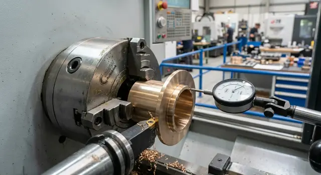
Before cutting, check end-face runout with an indicator. Check the working flange face, not some random edge with burrs. If the runout is already noticeable, the tool will not fix it. First remove the cause: an uneven seat, chips on the datum, too much jaw force, or contact against an unstable face.
The working order is usually this:
- Place the bushing on the first-operation datum and clamp without extra force.
- Check end-face runout and record the value before cutting.
- Remove the first light layer from the flange and check the flatness again.
- If the face moves, do not rush to final size. It is better to let the part release internal stress with one more small pass.
- Make the finishing pass at the end, once the part no longer changes face noticeably after material removal.
Here, a small pass is more useful than one “confident” removal. For bronze, that is often 0.1–0.2 mm per side, if the stock allows it. After each pass, look not only at the size, but also at how the flange behaves. Sometimes the diameter is perfect, but the face moves right after the second removal.
It helps to record after which pass the shift starts: pass number, depth of cut, runout before and after. After a few batches, a pattern appears. On the shop floor, this usually saves more time than a long discussion of already finished scrap.
If the batch is stable and the job is on CNC, it is better to make this check a normal part of setup. In serial metalworking, discipline in the second operation is often what decides whether the flange stays within size after removal from the chuck.
Example: the bushing holds size, but the flange moves
Take a simple part: a bushing body 80 mm long, outer diameter 42 mm, flange diameter 68 mm, and flange thickness 3 mm. The body size stays stable after machining, but the flange face shifts by several hundredths after removal from the chuck, sometimes even more. This is a typical situation: the cylinder still holds, but the thin disk no longer does.
For such a part, the first operation is better guided by the rigid bushing body, not by the flange. The outer diameter and the base end face are brought almost to size, and on the flange face a stock allowance is left, for example 0.15–0.25 mm per side. This allowance is not there just for safety. It allows the residual stress to be removed in the second setup, when the datum is cleaner and more reliable.
Then comes the second operation. The bushing is clamped by the finished datum, usually by the machined diameter or the bored hole through soft tooling. Then the remaining stock is removed only from the flange face, and if needed, the outer diameter of the flange itself is lightly finished.
The difference between heavy and moderate clamping is obvious here right away. If the jaws are tightened too much, the body of the bushing still holds its shape, while the flange already springs. While the part is in the chuck, the face seems flat. After removal, the flange relaxes, and end-face runout can grow, for example, from 0.02 to 0.07 mm. The body size remains within tolerance, so the defect stays hidden for a long time.
With moderate clamping, the picture is different. The part does not creep, the datum remains stable, and the flange changes shape much less after the finishing pass. On the same bushing, it is realistic to get end-face runout around 0.02–0.03 mm without fighting the cutting conditions.
The rule here is simple: clamp firmly where the part has section strength, and finish the thin flange only after re-clamping and with minimal force.
Which mistakes pull the part more
Usually, a part is ruined not by one big mistake, but by a chain of small decisions. Each one seems tolerable on its own. Together they create the classic case where the bushing holds diameter, but the flange shifts in face position or runout after removal.
The first common mistake is clamping by the flange because it is faster. For a rigid blank, that sometimes works. For a thin flange, almost never. The jaws press on the weakest part, the flange flexes, and after release it returns somewhere else than where you saw it in the chuck.
The second mistake is related to stock. If too little is left for the second setup, the machine no longer corrects the shape, but only repeats what came from the first operation. If the flange has moved a little, a finishing pass with a small removal just copies that curve.
Another mistake is bringing the finishing face in too early after roughing. After rough machining, stresses are still alive in the part, and the thin flange reacts to them immediately. If you bring the final size too soon, the next operation or even a simple flip changes the picture.
Many people look only at size after the second setup and do not check runout. That is a mistake that later eats up hours. Five minutes with an indicator often saves both the part and the batch.
It also works poorly to change clamping force from part to part. One operator tightens with a reserve, another is afraid of crushing the part and clamps softly. The program is the same, but the result drifts.
The shift is most often made worse by these choices:
- clamping on the flange instead of the more rigid cylindrical datum
- almost zero stock for the second operation
- early finishing of the end face
- working without checking runout after flipping
- different clamping force on identical parts
In a real shop, the pattern is often the same: on the first operation the bushing was brought in quickly, the flange was tightened more than usual, on the second operation 0.1 mm per side was left, and a nice surface was achieved. After removal, the face moved by several hundredths. The problem is not one pass, but the chain of decisions.
A short check between setups
If a part is moved to the second operation without a quick check, a small tilt quickly turns into flange shift. The cause usually sits not in the tool, but in the datum and the remaining stock.
Between setups, it helps to keep the same check order:
- Compare the overhang in the first and second setups. If the part sticks out farther the second time, the rigidity is already different.
- Check the datum surface. A small burr, chip, or mark from the previous operation already causes tilt.
- Look at the stock. The finishing size should still be where you planned it.
- Inspect the jaw marks. If they are too close to the working area, the metal near the clamping point is already stressed.
- Compare measurements while clamped and after release at the same points.
A simple rule works well: one operator measures in the chuck, releases the part, places it on a V-block or soft support, and repeats the measurement right away. If the difference repeats on two or three parts in a row, it is no longer a coincidence.
In practice, two causes show up most often: different overhang and a dirty datum. Jaws, cutting conditions, and the tool start getting blamed later, even though the problem is visible between setups already.
If your shop runs small batches, it is useful to put these five points directly into the route sheet.
Where to start in your own shop
Do not change everything at once. For a part like this, it is better to take one trial setup and test it on five blanks. That way it becomes clear much faster where the shift begins: under clamping, on the finishing pass, or after removal from the chuck.
First, make a simple measurement sheet. Record the bushing size, runout, flange thickness, and flatness at three points: after the first operation, after re-clamping, and after the final removal. Even such a short sheet often shows more than an argument at the machine.
It also helps to record the conditions under which the measurements were taken: what clamping force was used, how much stock was left for the second operation, the order of roughing and finishing passes, and which jaw set was mounted on the part.
After that, keep the process as stable as possible. Do not change the tool, cutting conditions, coolant, and blank material all at once. Otherwise it will be impossible to tell what actually shifted the flange.
Check the jaws separately. If you have two options, for example soft jaws bored to fit and more universal jaws, compare them on identical blanks from the same batch. Look not only at the size in the chuck, but also at what happens after release. Sometimes the part looks correct on the machine and moves only after a few minutes.
It is useful to fix the pass order as a route: clamp, remove rough stock on the outside, machine the face, leave stock on the flange, re-clamp, finish the base surfaces, and only then make the finishing pass on the flange. When the route is written down, the supervisor and the operator understand the task the same way.
If the part still shifts after those trials, the issue is no longer one setting, but the combination of machine, chuck, jaws, and datum scheme. In such cases, it helps to review the setup with an equipment and tooling engineer. EAST CNC and the east-cnc.kz blog both have practical materials on metalworking, and the company itself works with CNC machine selection, commissioning, and service. That is useful when you need more than a parameter tweak and want stable production across a series.
Start with five trial parts using one setup and rely on measurements. When the numbers are collected in one table, the answer usually appears faster.
FAQ
Why does a thin flange shift after being removed from the chuck?
Most often, it is not the tool that moves the flange but the clamping. While the bushing sits in the chuck, the jaws hold the shape. After release, the thin flange lets go of the stress and changes its face or end surface. This becomes especially noticeable with a long overhang, a thin wall under the jaws, and too much clamping force.
How can I tell if it is flange shift and not ordinary runout?
Runout shows the shift of the rotation axis. Flange shift often looks different: the axis may still be acceptable, but the flange face no longer holds its shape after release. Check the part not only in the chuck, but also after unclamping on a surface plate, a V-block, or during a gentle re-clamping. If the end face starts moving only after removal, look for the cause in clamping and the datum.
Could the problem be caused by overheating rather than clamping?
Heat causes the size to drift during cutting, and after cooling the dimension partly returns. Clamping-related shift appears at the moment of release. If everything looks straight in the chuck, but the face changes after removal, check clamping force, overhang, and the datum scheme first. Look at the cutting mode only after that.
What should I check on the drawing before the first setup?
First mark which surface sets the fit in the assembly and which end face works in the build. Then look at the flange thickness and the distance from the flange to the clamping zone. If the flange is thin and far from support, plan a gentle clamping force and leave stock for finishing on the second operation. The same allowance everywhere rarely gives a flat result here.
What is the best way to clamp the bushing in the first operation?
Hold the bushing by the rigid cylindrical section, not by the flange. For these parts, soft jaws usually give a straighter result if they are bored to the real clamping diameter. Reduce the force to the point where the blank no longer creeps at your cutting conditions. And keep the overhang as short as possible.
Should I bring the flange to final size in the first operation?
No, it is better not to rush. A finishing pass on a thin flange in the first setup often looks good only while the part is still clamped. Leave a small finishing stock on the flange for the second operation. That way you can relieve the residual stress on a more stable setup.
How much stock should I leave for the second operation?
Usually a small, even stock is left near the flange so the end face can be finished in the second setup. In the example from the article, the workable range for the flange face was about 0.15–0.25 mm per side, if the part geometry is similar. Choose the exact value based on the rigidity of the bushing and your route. The point is simple: after the first operation, you should still have material left to correct the shape, not just to reach size.
What should I watch in the second setup so I do not ruin the flange?
Set the part on the most stable datum you created earlier. Do not try to pull the flange flat with jaw force, because the picture will change again after release. Before cutting, check end-face runout on the working flange face, take a light cut, and measure again. If the plane keeps moving, do not go straight to final size.
What mistakes most often increase flange shift?
Most often, a part is ruined by clamping on the flange, almost zero stock for the second operation, and different jaw force from part to part. Another common mistake is checking only size and not the face after flipping. When several of these small issues combine, the bushing holds diameter, while the flange shifts by several hundredths.
Where should I start looking for the cause in my shop?
Start with one simple setup and test it on five blanks. Record the bushing size, end-face runout, flange thickness, and measurements in the chuck and after release. Do not change the jaws, tool, cutting conditions, and stock at once. Keep the conditions the same so you can see the real cause. Usually the picture quickly shows where the part starts to move: during clamping, after flipping, or on the finishing pass.