Large-diameter thread inspection in the shop without arguments
Large thread inspection: how to choose between a gauge, the three-wire method, and a measuring machine to settle shop-floor disputes fast.
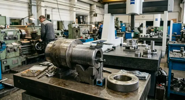
Why large threads often cause arguments in the shop
The argument usually starts not with the thread itself, but with the inspection method. One machinist takes a thread gauge and says, “it passes, so it’s good.” Another measures with wires and gets a value right at the upper tolerance limit. A third looks at the profile or pitch and says the part still raises questions. All three may be looking at the same part, but they are answering different questions.
A gauge is convenient for quick work. It gives a clear answer right at the machine and is well suited to in-process inspection. But it has limits. A gauge does not always show why a thread behaves oddly: whether the problem is in the mean diameter, the pitch, the profile angle, or the thread form. If the part is close to the tolerance limit, that answer is no longer enough.
With large threads, small errors matter more. A slight pitch drift, light out-of-roundness, a small taper, or an inaccurate profile form builds up over the length of engagement. On a small diameter, this may still be “forgiven.” On a large diameter, the same error can already interfere with assembly or give different results depending on the measuring method.
The most common situations where arguments arise are:
- the part is almost at the tolerance limit
- different shifts use different tools
- the gauge goes in hard, but it passes
- the wire measurement comes out “almost on size”
- the thread looks fine, but works poorly in assembly
There are also purely shop-floor reasons. The part may not have cooled fully. A burr may remain on the crest after machining. Someone measured closer to the start of the thread, while someone else measured in the middle. With a large diameter, these small things are no longer small.
So a dispute over a large thread is almost always not about whether the part is good or bad, but about how to prove it. If you do not agree in advance on what exactly is being checked and how, the same part can easily get two different verdicts.
What exactly is checked on this kind of thread
A large thread rarely has just one issue. The size may look correct, yet the part still may not assemble with the mating component or may run too tight. That is why inspection of large-diameter threads is not reduced to a single caliper measurement.
First, confirm what the drawing actually requires. Check the thread type, nominal diameter, pitch, tolerance class, thread length, and whether it is external or internal. Mistakes here are more common than they seem: a machinist measures a metric thread, while the drawing already specifies a different profile or tolerance class.
Then move on to the parameters that really affect assembly:
- mean diameter
- thread pitch
- profile angle
- surface form along the full length
The mean diameter is checked first. It is usually what decides whether the thread will mate smoothly or start to bind. The outside diameter alone says very little: the part may look “in size,” but the mean diameter may already be out of tolerance.
Pitch also cannot be treated casually. If it shifts even slightly, the thread flanks begin to drift out of sync with the mating part, and the problem may not show up on the first turn but after several turns. On large diameters, this is especially unpleasant: everything seems fine at first, and then the part starts to seize.
The profile angle is checked separately when there is doubt about the tool, setup, or insert wear. An incorrect angle changes the fit, increases friction, and often hides as a diameter error. Because of that, shop-floor debates often focus on tolerance, even though the real cause is elsewhere.
Geometry along the thread length is also checked. If the part has out-of-roundness or a slight taper, a measurement at one point may look fine, while another point does not. For long and large threads, this is normal, especially after heavy cutting or weak clamping.
And finally, the edges and the thread flanks themselves are inspected. A burr, dent, torn crest, or vibration mark can ruin proper assembly even when the numbers in the report are correct. That is why good inspection always combines two actions: measurement and a careful visual check of the part.
When a gauge is enough
A gauge works where you need a fast, clear answer: is the part good or not? For series production, this is often the best option. The operator does not waste time on calculations and does not argue over tenths where the task is simpler.
This approach works well if the tolerance is already clear, the thread is standard, and the process holds size steadily. On a CNC lathe, that is a common situation: the first part is checked carefully, the setup is not changed, the tool is in good condition, and then you need in-process inspection without delays.
A thread gauge gives a proper result only under one condition: the gauge itself must be in good condition. If it is worn, dirty, or not made for that standard, the argument starts right away. Then the problem is no longer the part, but the inspection tool.
The condition of the thread itself matters just as much. Chips in the groove, a burr at the entrance, or a nick after removing the part from the chuck - and the gauge can show a false picture. Before checking, it is better to quickly clean the thread and look at it visually. It takes less than a minute and saves a whole shift of discussion.
A gauge is usually enough if several signs match:
- parts are made in a series and give the same result one after another;
- the check is needed right at the machine, without a long stop;
- the GO and NO-GO gauges match the required standard;
- the thread is clean, without chips, crushing, or obvious impact marks.
For large-diameter thread inspection, this is especially convenient for repeating batches. If five, ten, or twenty parts in a row pass the same way, the process is probably holding within normal limits. In that situation, a gauge solves the practical task faster than any more complex method.
But do not expect more from it. A gauge separates good parts from bad ones very well. If you need to understand why the thread is tight, where the mean diameter shifted, or who is right in a dispute between departments, one gauge is no longer enough.
When the three-wire method is used
The three-wire method is needed when you do not want a simple “good or bad” answer, but an exact number. On the shop floor, that usually means one thing: you need the mean diameter, and the thread gauge no longer settles the issue.
A gauge is good for a quick check, but it does not show where the size shifted. If the result looks questionable, the debate starts immediately: one machinist says the part passes, another is unsure, and the process engineer needs facts. The three-wire method provides a measurement of the thread’s mean diameter that can be recorded and compared with the tolerance.
This method is most often used in these cases:
- the part is large and expensive, and it is better to catch an error before acceptance
- the part is one-off, with no room for rework
- the gauge gave a borderline or odd result
- the value needs to be entered into an inspection report
- the shop already has a micrometer and a suitable wire set
For large-diameter thread inspection, this is especially useful. On a large thread, a gauge can be heavy, awkward, or simply unable to answer all questions. Three wires and a micrometer let you check the size right at the machine or at the inspection station without a long wait.
The method works for both external and internal threads if you have the fixture and someone who can measure without rushing. The measurement itself is not difficult, but it requires care: the wires must seat correctly, the micrometer must not squeeze too hard, and the calculation must use the correct formula for the pitch and profile of the thread.
A good example is a large one-off part after finishing passes. The gauge does not go in as confidently as expected. It is too early to scrap the part, but accepting it is also risky. At that moment, the three-wire method often settles the dispute in ten minutes: you get a number, compare it with the tolerance, and then decide whether to keep the size or make one more pass.
If you need a documented result, this method is almost always better than a gauge alone. For the shop, it is a simple and practical compromise between quick inspection and accurate metrology.
When a measuring machine is needed
A measuring machine is not for “backup”; it is for when manual inspection no longer gives a clear answer. On large threads, this happens often: the gauge shows one thing, the micrometer with wires shows another, and the dispute is about a few hundredths.
The first common case is a complex profile or a very tight tolerance. If the drawing is too demanding for a simple pass/fail judgment, gauge checking alone is not enough. A machine helps you see not only the final result, but also exactly where the size is drifting: by mean diameter, pitch, profile angle, or thread form.
It is also needed when several parameters must be checked in one setup. On a large part, manual measurements are often collected separately: pitch in one check, mean diameter in another, runout in a third. Then these values do not always form a clear picture. A machine gives one report where all parameters are shown together.
Where manual measurement falls short
Short threads, threads near a shoulder, in a deep bore, or close to a step are often awkward for the three-wire method. The wires shift, the tool does not sit properly, and the operator has to “hold” the measurement by feel. In such cases, a machine is usually more reliable because it depends less on the skill and habits of a specific person.
If defects start appearing in the shop, a machine is especially useful. It helps find the cause, not just record the defect itself. For example, a part for a construction equipment assembly may fail to fit not because of the mean diameter, but because the profile is slightly off at the entrance or the pitch varies over a short section. A gauge often does not show that.
When the argument cannot be closed otherwise
If you need to compare the real thread form with the drawing, a measuring machine almost always wins. It shows where the profile differs from the design instead of reducing the discussion to “passes” or “does not pass.”
This is especially useful when accepting the first part, handling a complaint, or checking after a machine changeover. At these points, the cost of an error is higher than the time spent measuring. If you need not a quick answer but an exact analysis, it is worth using the machine right away.
How to check a thread step by step
Inspection of large-diameter threads is best done in the same order every time. Then the setter, inspector, and process engineer have fewer reasons to argue: everyone looks at the same drawing, with the same method, under the same conditions.
First, verify the thread designation on the drawing. Check the thread type, nominal diameter, pitch, and tolerance class. Mistakes here are more common than they seem: people measure the part correctly, but not the thing the documentation actually requires.
Then prepare the thread itself for measurement. Clean chips, oil, and stuck dust out of the flanks, and remove small burrs at the entrance. If you do not, the gauge may go in hard and the wires may seat unevenly. In the end, the part will look defective even though the problem is only on the surface.
Then it is convenient to proceed like this:
- Start with a thread gauge if that method is suitable for the standard and the part size.
- Check how the gauge enters: no misalignment, no extra force, no pulling it through by hand.
- If there is any doubt, measure the thread’s mean diameter with the three-wire method.
- Compare the result with the drawing tolerance, not with a feeling or with the previous part.
- If the numbers do not match or the thread form raises questions, send the part to a measuring machine.
A gauge is good for a quick shop-floor check. It saves time and immediately shows whether the part is suitable for normal acceptance. But with a large diameter, a long thread, or a borderline fit, one gauge is often not enough. Then the three-wire method gives a clearer picture of the mean diameter. It is slower, but it helps show where the size moved.
A measuring machine is not used “just in case,” but when the dispute needs to be settled with facts. For example, the gauge passes inconsistently, while the wire measurement sits on the tolerance limit. The machine helps reveal the profile, pitch, and geometry along the thread length when simple tools can no longer give the answer.
At the end, always record what exactly was used to measure the part, at what temperature, and what result was obtained. One short note in the route sheet or report often saves more time than rechecking the entire batch. For a shop where parts come off CNC lathes after turning, this order is usually the calmest and clearest.
Where mistakes happen most often
On a large thread, a small mistake quickly turns into an argument. A difference of a few hundredths can already change the conclusion: is the part good or not? So the problem usually does not come from the machine, but from the way people check the size.
One of the most common causes is using a thread gauge of the wrong tolerance class. In the shop, this happens all the time: the gauge looks similar, the marking is only glanced at, and then one shift says “it passes” while another says “it does not pass.” For large-diameter thread inspection, this is especially unpleasant because reworking such a part is expensive.
Checking immediately after cutting causes no less trouble. Oil, fine chips, abrasive dust, and a burr at the entrance remain on the flanks. To the eye, the thread looks clean, but the gauge already goes in more tightly and the wires seat unevenly. If the part has just come off a CNC lathe, it is better to clean the profile and remove burrs first, and only then measure.
People also often make mistakes with measuring force. A micrometer is often “pulled tighter for safety,” especially when the size is close to the limit. As a result, the wires are pressed a little, the hands add extra force, and the measurement of the thread’s mean diameter shifts downward. On a large thread, this can easily give a false rejection.
The three-wire method is also often spoiled by small things. The most basic mistake is using the wrong wire size. Sometimes a set lying nearby is taken without checking it against the thread pitch. Formally, the measurement was done correctly, but the number can no longer be compared with the calculation. If the pitch is large, the error shows up immediately. If the pitch is intermediate, it may stay hidden for a long time.
Another weak point is the drawing. People compare the result with a printout that does not show the full thread designation, does not specify the tolerance class, or is an outdated revision. After that, they argue not about the measurement, but about who saw which document. The machinist uses one note, the inspector another.
Usually, a simple routine helps:
- check the gauge marking and its class
- clean the thread and remove the burr at the lead-in
- make sure the wire size is correct before measuring
- use the micrometer without extra force
- compare the result only with the full drawing
If the shop follows this routine, there are noticeably fewer arguments. And the most useful part is simple: it is better to spend three minutes on preparation than an hour later figuring out who made the mistake.
A short shop-floor example
A shaft with a large external thread was being turned for a heavy assembly. After machining, the operator took a thread gauge and saw something unpleasant: from one side the gauge went in normally, but from the other it stopped almost immediately. He decided the part had to be scrapped.
The setter disagreed. He looked at the last parts in the batch and suspected not a full-profile defect, but a tool wear issue. It was a typical dispute: the operator trusts the gauge, the setter blames the cutter, and there is little time to sort it out.
To avoid guessing, the part was checked more precisely. The three-wire method showed that the measurement of the thread’s mean diameter was within tolerance. That already changed the discussion. If the mean diameter is within spec, the reason for the tight gauge fit is often not size alone.
After that, the shaft was put on a measuring machine. It showed a slight taper along the thread length. At one end, the profile still held the required geometry, while at the other end the size drifted enough for the gauge to start binding. The cause was found quickly: the tool holder was worn, the cutting tool started working with a slight offset, and the error accumulated along the length of the pass.
In the end, the part was not written off immediately, and it was not accepted just because the mean diameter passed by the wire check. The decision was made based on the defect cause. For one part, that meant an individual assessment based on use and assembly risk. For the batch, it meant replacing the holder, checking the offset, and rechecking in several sections.
This kind of case shows well how inspection of large-diameter threads should work in the shop. The thread gauge quickly catches the problem, the three-wire method refines the mean diameter, and the measuring machine helps explain the error form. When each method answers its own question, the argument ends faster than the usual back-and-forth at the machine.
A quick check before handing over the part
Most disputes come up in the last couple of minutes before the part is handed over. Usually the problem is not the thread itself, but the small things: the wrong size was taken from the card, an old gauge was used, or the hot part was measured immediately after machining. For large-diameter thread inspection, this final check saves both time and nerves.
First, verify the thread designation. The marking in the route card, on the drawing, and on the part tag should match in diameter, pitch, tolerance class, and thread direction. A mistake in one line can easily turn into an acceptance dispute, even if the machining was fine.
Then look at the measuring tool. The thread gauge must have valid calibration or verification, with no dents and no obvious wear on the working surfaces. If the size was checked not with a gauge but with the three-wire method, the record should immediately note the wires, the calculation, and the result of the thread’s mean diameter measurement. When inspection was done on a measuring machine, that should also be recorded without vague wording like “checked.”
A quick check usually looks like this:
- verify the thread designation in all documents;
- check the date and condition of the gauge or other tool;
- inspect the lead-in thread under a magnifier;
- make sure the part and the tool are not too far apart in temperature.
The lead-in thread often spoils the impression of the whole part. It can hold a burr, a dent from part removal, or a mark from a poor tool entry. Because of that, the gauge may go in hard, and the argument starts not about tolerance, but about one damaged thread.
Temperature is also often underestimated. A large part can stay warm longer than it seems after the machine. If the gauge is cold while the part still holds heat, the result can easily shift by several hundredths, and on a large thread that is enough to raise doubts.
The last step is simple: record exactly what was used and what was obtained. One line in the card, such as “GO gauge - acceptable” or “three-wire method, mean diameter within tolerance,” closes half of the unnecessary questions before the part is even handed over.
What to do next
If inspection of large-diameter threads regularly ends in arguments between the operator, the setter, and quality control, the reason is usually simple: the shop does not have one accepted inspection routine. It is better to set that routine in advance for each thread type. Separately for external and internal threads, and separately for series parts and first-off parts after changeover.
For some parts, a thread gauge is enough. It is fast and works well for production flow. But where the tolerance is tight or the customer asks for exact numbers, that is not enough. The inspection card should state right away when only a “good/not good” answer is needed and when measurement of the thread’s mean diameter is required.
A short scheme works well:
- inspect a series part with a clear tolerance using a gauge;
- inspect the first part of the batch and the part after setup changes more precisely;
- send disputed cases to the three-wire method;
- check complex requirements and complaints on a measuring machine;
- record the result in the same format for all shifts.
Another simple step is to keep a full set of wires in the shop for the threads that most often cause questions. If they are not at hand, the dispute is usually settled “by eye” or delayed until the lab. Both options are poor. Wires, a proper micrometer, and a clear calculation table often save more time than rechecking an already finished batch.
If you are choosing a machine or a line for threading operations, it is better to discuss inspection requirements right away. This concerns not only tolerance, but also who will measure the part, by which method, and how often. For such tasks, talking with EAST CNC is appropriate already at the equipment selection stage: the company supplies CNC lathes and metalworking lines, which means inspection can be tied to the process itself, commissioning, and future service.
Usually, one document of 1-2 pages is enough. It should include the method, the tool, the inspection frequency, and the action for a disputed result. After that, there are noticeably fewer unnecessary conversations on the shop floor and more clear decisions.