Interrupted Cutting Inserts: How to Choose Without Trial and Error
Interrupted cutting inserts are chosen based on impact load, geometry, and grade. Here is a simple step-by-step way to choose without endless trial and error.
Why interrupted cutting breaks an insert faster
In interrupted cutting, the cutting edge doesn’t stay in contact with the metal continuously. It enters the material, leaves it for a moment, and then takes another impact. Each entry loads the thinnest part of the insert.
In normal continuous cutting, the load is more even. The edge enters the metal once and then removes chips without sudden spikes. It still heats up and wears, but that wear usually develops gradually and is easier to predict.
Interrupted cutting is harsher. The cutting force rises sharply on entry, drops on exit, and then rises again. The edge is no longer dealing with smooth wear, but with repeated impact. If the part has a groove, hole, casting scale, or broken surface, the insert takes that hit on every revolution.
That’s why chipping often appears before ordinary wear. The edge doesn’t get time to “age” evenly on the flank. First come microcracks or tiny breakouts, then a piece of the cutting edge breaks away. The insert may still look fine from the outside, but it will no longer cut properly.
The problem is usually easy to spot. Small chips appear on the edge, the cutting sound turns harsh, the part surface tears, and the spindle load starts to jump noticeably. People often blame feed or speed first, even though the real cause is the nature of the contact itself. If the edge keeps striking metal after every interruption, the conditions are much harder than in normal turning of a solid surface.
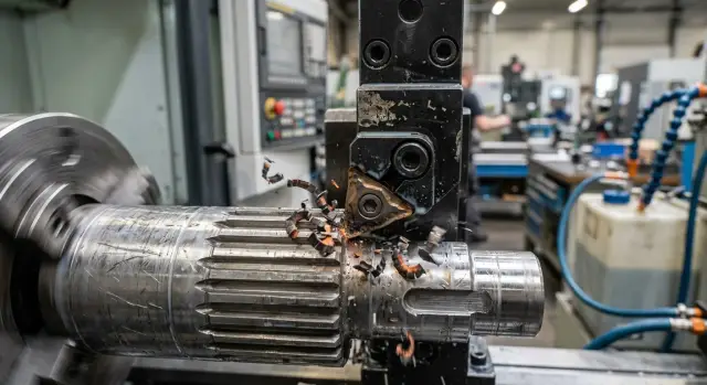
You can see this clearly even on a simple part with a groove. While the tool moves over a continuous section, cutting is calm. As soon as it crosses the groove, the edge gets a series of identical impacts. If the insert is too sharp or too brittle, chipping shows up before normal wear becomes visible.
What counts as impact load
Impact load happens when the cutting edge is not removing a smooth solid piece of metal, but periodically entering the material or leaving into empty space. For an insert, this is not just a heavy cutting mode. It is a short, sharp blow that repeats again and again.
Grooves, holes, windows, keyways, and sudden changes in section usually create this effect. The same goes for casting scale, a hard surface layer after forging, and uneven stock allowance, where one area of the blank has more metal than another. If the edge enters and leaves the material several times in one revolution, the risk of chipping is already high.
The rigidity of the whole setup matters too. A short toolholder clamped firmly handles entry into the cut more calmly. A long overhang makes the impact worse: the tool flexes slightly, then springs back and hits the edge harder. Weak part clamping does the same thing. The workpiece shifts, and the insert takes not one clean hit, but a series of smaller blows.
How to tell impact from ordinary vibration
A strong impact is usually heard as a clear click or knock at the same point in each revolution. After that, a local chip is often visible on the edge, as if a tiny piece were bitten out at one spot. On the part, you often see repeated marks exactly where the edge enters and exits.
Vibration behaves differently. It creates a hum, surface waviness, and more even wear. The edge usually doesn’t chip right away; it dulls or crumbles along a section of the edge. If the sound gradually gets louder with feed and isn’t tied to a groove, hole, or hard crust, it is more likely vibration than a clean impact.
A quick check before the first part
Before a trial run, it’s enough to answer a few simple questions. Are there grooves, holes, or windows along the tool path? Is there a hard crust or uneven stock allowance? Is the tool overhang too long and the part clamped securely? Does the edge enter the material immediately at a high feed?
If at least two of these apply, it’s better to treat the job as an impact cut right away. That’s a useful starting point: it becomes clear that the usual “set it up like a solid cut” approach often ends in chipping here.
How insert geometry behaves under impact
When the tool cuts solid metal, the edge works steadily. When it enters a groove, hole, or keyway, the picture changes: the edge cuts, then takes an impact, then cuts again. At that moment, insert geometry can matter more than the values in the table.
Sharp edge and strong edge
A sharp geometry cuts easily. It enters the metal faster, heats the cutting zone less, and often gives a cleaner surface. But that kind of edge has less strength in reserve. If the part is shaky, there’s play in the chuck, or the feed is too aggressive, the thin edge chips faster.
This is usually how positive geometry behaves. It reduces cutting force, which is useful for thin-walled parts or weak clamping. But in interrupted cutting, an easy entry doesn’t always save you. If the impact is sharp, the edge doesn’t have time to deform — it simply breaks out.
A stronger geometry is rougher, but it handles impact better. The edge is thicker, the support behind it is stronger, and the insert tolerates entry and exit from the cut more calmly. The trade-off is simple: the tool pushes harder on the part. If clamping is weak, you’ll get vibration, size drift, and marks on the surface.
The rule is simple. If the part is rigid, the machine is rigid too, and the impact is noticeable, a stronger geometry is often the better choice. If the part is thin and easy to deflect, too heavy a geometry will create problems of its own.
Nose radius and chipbreaker
The nose radius also changes the edge behavior a lot. A small radius cuts more softly and reduces pressure, but the tip itself is more fragile. Under impact, it chips more often. A larger radius handles entry into the metal better and is less sensitive to local impact, but it increases cutting force noticeably. If the machine or part can’t hold the load well, chatter starts.
On a part with a groove, this is easy to see. A small radius may give quiet, clean cutting until the first hard entry. A larger radius survives that entry more calmly, but if the clamping is weak, it starts humming along the whole pass.
Chipbreaker shape also affects the result. An aggressive chipbreaker helps cut more easily, but its edge is often more delicate. A calmer, heavier shape is more reliable, but it needs a stiffer setup. So for interrupted cutting, it’s better to choose an insert not by one feature alone, but by a combination of three things: edge strength, nose radius, and chipbreaker shape should all match your impact and your machine rigidity.
How insert grade affects chipping
In interrupted cutting, the winner is often not the hardest grade, but the tougher one. Impact loads the cutting edge in bursts, and a brittle insert often crumbles before it can show good wear life.
A hard grade works well where cutting is smooth, the part is stable, and feed and speed don’t jump around. In those conditions, it holds size longer and wears more slowly. But on a part with a groove, casting scale, or changing section, the same grade may chip on the first few passes.
A tougher grade handles impact more calmly. Yes, it usually wears faster on the flank, but the edge doesn’t fall apart at every entry into the metal. If you don’t have much information yet and there’s no time for a long trial run, that is often the smartest starting point.
Where coating helps, and where it doesn’t
Coating reduces friction, helps control heat, and can slow wear. That is useful, but coating doesn’t fix a weak base material. If the grade itself is too brittle for the impact, a hard coating won’t save the edge from chipping.
In practice, the mistake looks like this: the operator chooses a very hard grade expecting long life, sees a clean surface at the start of the pass, and then gets a chip on the way out of the groove. After that, people usually blame the feed or the workpiece, when the cause is simpler — the grade base can’t handle that impact load.
If the conditions are still unclear, it’s better to start with a grade that resists chipping. It’s not the boldest choice, but it almost always saves time. First get a lively, predictable edge, and only then try a harder grade if you want more wear resistance.
It’s best to compare grades one at a time. Change only the insert grade and keep the geometry, feed, speed, and tool overhang the same. Otherwise, you won’t know what actually made the difference.
A simple guide: if the edge crumbles too early, choose a tougher grade. If there’s no chipping, but the insert wears out too quickly, you can move toward a harder grade. If the result becomes smoother after changing the grade at the same settings, you’re going in the right direction.
A selection process without unnecessary trials
If the edge meets empty space and then cuts into metal again, the insert lives by different rules. In this kind of work, people often make mistakes not in the settings, but in the order of selection. When the steps are followed one by one, the working option appears faster.
First, look at the part itself, not the catalog. You need to find all places where the edge enters and leaves the cut: groove, hole, casting scale, keyway, interrupted profile. That is where impact load is born. If there are several such zones in one revolution, the risk of chipping rises sharply.
Then assess the rigidity of the whole chain honestly. The machine, chuck, toolholder, and the part itself all work together. If the toolholder sticks out too far and the blank is thin and springy, even a good insert grade won’t save you. In practice, the weak point is often not the insert at all, but the clamping or the tool overhang.
After that, choose geometry for the impact, not for the easiest chip removal. A very sharp, thin edge cuts lightly, but on interrupted cutting it often chips first. A stronger geometry with a reinforced edge usually handles entry into the metal more calmly. The cut may become a little heavier, but the tool lasts longer and behaves more predictably.
The same logic applies to the grade. Don’t look only at the workpiece material — look at the strength of the impact too. If you’re torn between wear resistance and toughness, toughness is often the better choice for interrupted cutting.
A practical sequence looks like this:
- Find the zones where the edge enters and exits the cut.
- Check the rigidity of the machine, chuck, toolholder, and part.
- Choose a geometry that can handle impact.
- Pick a grade that fits the material and the impact character.
- Start with a moderate setting and change only one parameter at a time.
That last step is often skipped, and that’s a mistake. If you change feed, speed, and depth of cut all at once, you won’t know what actually helped or hurt the result. In interrupted cutting, it’s better to start calmly, make several passes, and inspect the edge after each change.
A simple example on a grooved shaft
Take a typical shaft with a keyway. From the outside, the part looks simple, but for the tool it is no longer a solid surface: the edge cuts the metal, then briefly leaves into the empty groove, and then cuts into the metal again. At that moment, it gets a short impact.
If you use an insert with a very sharp geometry, the first result often looks good. The chip flows easily, the surface on the smooth section is cleaner, and the load on the machine is lower. But the thin cutting edge handles repeated re-entry into the metal at the groove poorly. A small chip appears at the corner quickly, then it grows and starts leaving a mark on the part.
This often happens on the first trial: a good result on the solid section creates the false impression that the choice is right. Then the tool reaches the groove, the sound gets harsher, and tool life drops sharply.
On such a shaft, a stronger geometry usually works better. It isn’t as sharp, but the wedge is thicker and the cutting edge area is stronger. If you add a tougher grade, the edge handles the impact load better and is less likely to chip.
The surface after this change may be a little less mirror-like on the first pass. But the final result is usually better: the edge lasts longer, the size holds more evenly, and the risk of a sudden chip at the groove is much lower. For interrupted cutting, that’s a normal trade-off — slightly less aggressive cutting in exchange for reliability.
If the shaft is long and starts ringing at speed, don’t blame the insert right away. First shorten the tool overhang as much as the setup allows. Then slightly reduce the cutting speed. Even a small reduction often removes the extra impact when the tool re-enters the metal.
Mistakes that most often lead to chipping
Chipping is rarely caused by a bad insert alone. Usually, the reason is a combination of mistakes: a grade that is too hard, geometry that is too sharp, weak clamping, and rushing the speed. In interrupted cutting, a small mistake becomes expensive very quickly.
One of the most common mistakes is choosing the hardest grade just for longer tool life. On a continuous pass, that sometimes works, but under impact such an insert often chips sooner than a tougher one.
The second mistake is geometry that is too sharp. It cuts easier and more smoothly, but it handles repeated impacts worse. For a part with frequent entry and exit from the cut, it’s better to start with a stronger edge.
The third mistake is changing everything at once. People install a different insert, increase speed, adjust feed, and then try to figure out what exactly broke the edge. That approach shows almost nothing. Change one parameter at a time.
Another common error is blaming the insert when the problem is in the setup. Weak part clamping, a long tool overhang, play in the toolholder, or workpiece runout hit the edge harder than people think. If the chip appears in the same place every time, check the rigidity of the system first.
Speed is another thing people rush. Until the edge passes into the cut calmly at a moderate setting, it’s too early to add more meters per minute. First you need a stable start with no chipping on several identical parts. Only then does it make sense to raise speed in small steps.
A short check before starting
Interrupted cutting doesn’t forgive a random start. On the settings sheet, everything may look fine, but the first meeting between the edge and a groove, hole, or hard crust quickly reveals the weak point.
Before the first pass, it helps to check five things quickly. Look at the part and mark all the interrupted-cut zones. Assess the part clamping and tool overhang. Check whether the geometry chosen for impact entry is too sharp. Don’t start with a high speed on the first part. And change parameters one at a time so the cause of the result is clear.
There is also a simple clue after the first part: remove the insert and inspect the edge with a magnifier. Small breakouts usually point to impact. Even wear means the choice is on the right track. After that, you can raise the speed carefully instead of looking for a new insert after every pass.
What to do next
On the shop floor, it helps to keep not the whole catalog, but a few clear starting combinations: geometry plus grade. Usually two or three options are enough — one for moderate impact, one for a harder entry into the cut, and one for parts with grooves, casting scale, or uneven stock allowance. If the same part repeats from batch to batch, that set quickly saves both inserts and time.
To keep the process from going in circles, record short notes. It’s important to write down exactly where the edge chips, after how many parts it happens, and which combination was in use. That alone is enough to see a repeating pattern. If the insert consistently chips after leaving the groove, the issue may not be the insert at all, but the overhang, clamping, or chuck runout.
When the problem comes down to equipment, it’s worth looking wider than the cutting tool alone. If chipping repeats with different inserts and the cause is clearly tied to machine rigidity or setup, it makes sense to review the system itself. At EAST CNC, you can discuss machine selection for the part, commissioning, and service support. In cases like this, that is more useful than endlessly changing grades and geometry blindly.
Once you build the right working setup, the shop runs more calmly. Instead of random trials, you’ll have a short, reliable set of solutions for repeat parts.
FAQ
Why does interrupted cutting wear out an insert faster?
Because the cutting edge doesn’t cut the metal smoothly — it keeps re-entering it after a gap. On entry, the load rises sharply, and the insert takes repeated impact. That’s why chipping often appears before normal wear.
How can I tell impact load from ordinary vibration?
Look at the location and the sound. Impact usually creates a sharp knock at the same point in each revolution, and the edge shows a local chip. Vibration more often creates a hum, surface chatter, and wear stretched along the edge.
What insert geometry should I choose first for a grooved part?
On a part with a groove or hole, it’s often better to start with a stronger geometry rather than the sharpest one. Such an edge cuts a little heavier, but it handles entry and exit more calmly. If the part is thin or the clamping is weak, don’t choose something too heavy.
For impact loading, should I choose a hard or tough grade?
With impact, a tougher grade usually wins. It may wear faster, but it typically keeps the edge intact longer than a very hard and brittle grade. If there’s no chipping but wear is too fast, then try a harder grade.
Do I need a large nose radius for interrupted cutting?
A larger nose radius usually handles local impact better because the tip is stronger. But it pushes harder on the part and can cause chatter if the setup is weak. For a first try, choose a moderate radius, not an extreme one.
Will coating help if the insert is chipping?
By itself, coating won’t save an insert from chipping if the base grade is too brittle. It helps reduce friction and wear, but the cutting edge and the insert material take the impact. First choose the right grade and geometry for the impact, then look at coating.
What should I change first if the edge chips on entry into a groove?
First check the tool overhang, part clamping, and where the tool enters the metal. Then lower the speed and keep a moderate feed if it isn’t too aggressive. If the chip still appears, switch to a stronger geometry or a tougher grade, but change only one thing at a time.
Can I increase speed right away if the smooth section cuts cleanly?
No — on interrupted cutting, a clean mark on a smooth section can be misleading. The insert may work fine until the first hard entry into a groove, then chip quickly. First get stable performance on several identical parts, and only then raise the speed little by little.
How can I quickly check whether the insert choice is correct?
After the first part, remove the insert and inspect the edge with a magnifier. Small edge breakouts and a local chip usually mean the impact is too harsh for it. If wear is even and the sound doesn’t turn harsh, the choice is moving in the right direction.
When is the machine or clamping the real problem, not the insert?
When the same chip appears in the same place even after changing the insert, look for the cause in the setup. A long overhang, weak clamping, holder play, and workpiece runout hit the edge harder than they seem to. In that situation, a new insert rarely solves the problem for long.