How to Read a Part Shape Map After Unclamping
A part shape map after unclamping shows more than size alone. Learn which points to measure right after release and after cooling.
Why size alone is not enough
One diameter or one length still does not show what the part became after unclamping. In the report, the size may be within tolerance, but the geometry itself may already have shifted.
Clamping holds not only size, but also shape. While jaws, V-blocks, or a steady rest are pressing the blank, they partially hide bend, out-of-roundness, and axis shift. After release, the support disappears and the metal begins to redistribute internal forces in its own way.
Residual stresses do not disappear in one pass. They show up when the part is freed from pressure. So one diameter may stay normal, but the axis has already moved, the face may have warped slightly, the hole may have lost coaxiality, and a round profile may be closer to an oval.
This is easy to see on a thin-walled bushing. It is taken off the machine, the internal diameter is measured in one section, and the result looks fine. Then the part cools, and the size near the edges is already different, while the hole axis shifts enough to cause misalignment during assembly.
Shape drift is strongest in parts with uneven stiffness: thin walls, long shafts and bushings, parts with slots, windows, and cutouts, as well as blanks after uneven stock removal, heat treatment, or rough machining. The reason is simple: where there is less metal, the part resists unloading less effectively. A slot or deep cutout also changes how the section works. It no longer behaves like a solid cylinder or a massive housing.
So the main question is not what one size came out to be, but what the part became after it was released. For production, that matters more than it seems. You can get a "good" diameter and still lose the fit, runout, or straightness.
If a part starts living its own shape after unclamping, checking only one point gives false confidence too early. You need not one number, but a picture across several sections and surfaces.
What changes in the first minutes
Right after unclamping, a part often changes shape rather than size. The metal releases part of its stress, and the wall, face, or hole moves by a few hundredths of a millimeter. On thin and long parts, this is visible almost immediately, sometimes within 2-5 minutes.
That is why the first map is taken without delay. If inspection is postponed, it becomes impossible to tell what came from the clamping force itself and what happened during cooling and while the part was sitting freely.
In the first minutes, it is important to check the same points you will repeat after cooling. That way you see not a random number, but the movement of the shape.
Usually a simple set is enough: measure the main sizes in 2-3 sections along the length, check runout on the outer and inner surfaces, look at the face in at least 3-4 points around the circumference, and record the part temperature and the shop air temperature right away.
It is better to take the main sizes quickly and in the same order: near section, middle section, far section. If the part behaves unstably, the difference between sections tells you more than the size in the middle.
Runout works the same way. The outer diameter may barely change, but the axis is already moving. The inner surface often drifts more, especially after boring. The face should not be checked in just one spot either. Several positions around the circumference quickly show tilt or a slight "dish" shape.
Temperature is often not recorded, and that is a mistake. After machining, the part is often noticeably warmer than the shop. Even a few degrees change size and can hide deformation. Two short notes — part temperature and air temperature — make root-cause analysis much easier later.
A simple example: a thin-walled bushing holds its size right after release, but outer runout grows from 0.01 to 0.03 mm. Twenty minutes later, the size is almost the same, but the shape has shifted even more. If the first measurements were saved, the reason is clear right away: the part started changing shape before it fully cooled.
Which points to measure right after unclamping
After unclamping, shape changes unevenly. So the first points should be chosen for meaning, not convenience. First, look at the zones where the jaws, clamp, or center were just holding the part. That is where a circle often becomes oval, a cylinder starts to "drift," and a face lifts at the edge.
But one zone is not enough. You also need a second group of points on the free end of the part. If the area near the clamp has barely moved, but the free end has shifted by several hundredths, the part is unloading along its length, not only at the contact zone.
Along the length, it is best to take at least three sections: start, middle, and end. On a short part, that is usually enough to see where the shape breaks. One diameter in the middle easily misses taper, bending, or a local pull near the edge.
At each section, it helps to repeat the same angles: 0°, 90°, 180°, and 270°. This cross pattern quickly shows the deformation type. If the 0°-180° pair diverges while 90°-270° stays almost unchanged, that is not random scatter, but a directed change, often linked to clamping.
It is worth checking weak spots separately: slots, holes, windows, cutouts, and thin walls. These areas behave differently even when the overall size is still within tolerance. Here it is better to place points on both sides of the feature, not just one mark nearby. That way you can see whether the shape is being pulled one way or whether the area is opening symmetrically.
A minimal layout is usually enough: three sections along the length, four points around the circumference at each section, plus separate points in the clamping zone and around weakened areas. If the part is long or thin-walled, add one more intermediate section. Two extra minutes of measurement often save an entire batch.
What to check after cooling
Once the part has cooled to shop temperature, the inspection scheme must not change. You need to measure the same sections and the same angles as right after unclamping. Otherwise you are comparing different places and getting a false picture.
Cold inspection shows not only how much size drifted, but also how the part rebuilt its shape. The diameter may almost return within tolerance, while ovality grows. Or taper may become smaller, but runout on the reference surface may increase. So you should look not at one number, but at a set of parameters.
Usually four things are summarized together: ovality for each section, taper between the end sections, radial or face runout relative to the chosen base, and the position of the profile center compared with the first measurement.
Center shift is often missed. That is a mistake. If the part unloaded asymmetrically, the center of the hole or outer diameter may shift by several hundredths even when the average size barely changes. For fits and coaxiality, that can be worse than a simple diameter drift.
It is useful to note where the shape has already settled and where it is still creeping. If ovality barely changes after cooling in one section but grows from batch to batch in another, the problem is usually not the measurement. More often the cause is local stress, stock allowance, or the clamping scheme.
Hot and cold measurements should not be mixed in one column without a note. "Right after unclamping" and "after cooling" are two different states of the part. They should be stored separately and then compared as two maps of the same geometry.
A simple rule works well. If only size changes after cooling, first look for a thermal effect. If ovality, runout, and center position change, look deeper: residual stresses, uneven stock removal, and clamping stiffness.
How to create a shape map step by step
A single measurement does not tell you much. To understand how the part behaves, you need a repeatable inspection method.
First, choose a base and do not change it until the end of the series. If on the first part you reference the face and hole, but on the fifth you switch to the outer diameter, the numbers cannot be compared. That is why it often seems like the shape is drifting more than it really is.
Then make a simple sketch and mark the measurement points on it. Usually you take several sections along the length and repeat the same angles in each one. For a round part, 0°, 90°, 180°, and 270° are often enough. For a flat part, the logic is the same: the same zones and the same inspection order.
Take the first set of measurements right after unclamping. Do not stretch the process out. If one part is measured after one minute and another after seven, those are already different states.
One method for the whole batch
After the first measurement, let all parts cool for the same amount of time. Not 10 minutes for one and 30 for another. If shop temperature fluctuates, set a simple standard: repeat the measurement only after the part has equalized to the normal temperature for the area. That makes it easier to separate thermal drift from shape change caused by internal stress.
Then repeat the measurements in the same places, with the same tool, and in the same order. When the operator jumps from point to point, they add their own scatter.
To avoid getting buried in numbers, put the result into a table right away. Usually five columns are enough: part number, section and point angle, size right after unclamping, size after cooling, and the difference between the two measurements.
When the data is arranged by sections and angles, the picture becomes clear quickly. If only one area moves, look for local stress or a weak zone. If opposite points diverge, look at ovality, bending, or shift after release. After just a few parts, you can see where the process is stable and where the part keeps changing shape.
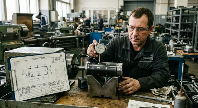
Example with a thin-walled bushing
A thin-walled bushing often fools inspection. In the chuck after boring, it holds size evenly, and the indicator looks calm. But once the jaws release the wall, the metal redistributes stress, and the part is no longer what it was a minute ago.
A typical picture looks like this: the outer diameter barely moves. If you look only at that, the process seems stable. The problem is usually hidden inside.
Right after release, it is better to check not one internal size, but several sections along the length and at least two directions in each one. For a bushing, that is usually enough: the inner diameter near the clamping zone, in the middle of the length, and near the free end, with the outer diameter checked in the same sections for comparison.
Very often the result is this: near the clamping zone, the inner diameter becomes oval within the first few minutes. Along the 0° axis it is still within tolerance, but along the 90° axis it shifts by several hundredths. If the inspector checks only one point or uses only a go/no-go check, this defect is easy to miss.
Then the part cools and keeps changing. After 15-30 minutes, the ovality near the edge may decrease, but move toward the middle of the length instead. That is an important point. The shape changes not only in magnitude, but also in location. One measurement right after release shows one picture; a repeat after cooling shows a different risk zone.
In practice, it is convenient to mark three bands along the length and take at least two directions in each one. Then you can see where the hole turned into an ellipse and where that ellipse shifted later. You cannot see that from one number in the report.
That is why a shape map is more useful than a single size. It shows not just "good/bad," but how the bushing behaves after release. For thin-walled parts, that is often more important than the boring operation itself.
Where mistakes happen most often
Inspection mistakes often happen not at the machine, but at the measurement table. The part is removed, one diameter is checked quickly, it looks within tolerance, and everyone assumes it is fine. Then half an hour later the shape shifts, and the picture is different.
The first common mistake is measuring one size in one section. That makes it easy to catch a good diameter and miss ovality, taper, or a local wall shift. If the part changes after release, one number is not enough.
The second mistake is related to the base. The indicator is placed on a dirty support, a burr, or a spot that was already slightly damaged by a previous touch. The instrument honestly shows a deviation, but the part is not moving — the measurement setup is. The base must be clean, stable, and the same for the whole batch.
The third mistake is different inspection timing. One part was checked right after release, another after 20 minutes, and a third only when cold. Then it all gets placed in one table and someone tries to find a pattern. That table usually mixes only different temperatures and different stages of metal unloading.
Another common mix-up is taking the clamping mark for the whole deformation. A local imprint is visible on the surface, and it is treated as the cause of the entire shape error. But the jaw mark may be local, while axis shift or bending appears for another reason. If you do not separate a local defect from the overall geometry, you start correcting the wrong process.
There is also a quieter mistake: different measuring force. One inspector touches a thin wall lightly, another presses a bit harder, and the needle already moves by several hundredths. For a rigid part, that is minor; for a thin bushing or housing, it can be a real difference.
The working rule is simple: the same base, the same time after release, the same force, and several points instead of one. Then the picture is honest, and deformation becomes visible right away.
Quick checklist before making a conclusion
Before drawing a conclusion from the measurement, pause for a minute. Mistakes often come not from the machine or the clamping, but from different inspection conditions.
Check five things:
- is the time after release the same for all parts;
- do the base, section, length step, and point angle match;
- are the part temperature and shop temperature recorded;
- can you see where the shape starts to drift;
- does the same pattern repeat on at least a few parts.
Most often, the problem hides in the first two points. One part was measured immediately, another was left on the table and checked later. On paper, that looks like different deformation, when in fact the only reason is the pause between operations.
A point shift by even a couple of millimeters, or a different setup angle, also breaks the comparison. For a cylindrical part, that is already enough to get a different picture, especially if you are looking for the start of ovality or bending.
Many people forget to record temperature for no good reason. After machining, the part cools unevenly, and inspection after cooling may show a different profile than inspection right after release. Without that note, it is hard to tell what changed: the shape, the cutting conditions, or just the thermal state.
If even one point does not match, do not rush to change cutting parameters, clamping force, or the program. First repeat the measurements under identical conditions. Only then does the map start to tell the truth.
What to do next on the shop floor
If the part starts to shift shape right after unclamping, do not rush to change cutting parameters. First check the clamping setup and the allowance for the finishing pass. Often the problem is not the size, but the fact that the supports and jaws hold the part in a way that lets it return to its natural state after release.
If the shape changes not immediately, but after 10-30 minutes or after full cooling, you should look at the whole process route. Where a large amount of metal was removed, after which operation the part heated up most, whether material was removed unevenly from different sides — all of this affects the result more than one control size.
One part proves almost nothing. You need a batch of at least 5-10 pieces measured under the same conditions. Only then can you see repeatability instead of a random failure.
In practice, the scheme is simple. If the part moves immediately, review the clamping, support points, and allowance for finishing. If it moves after cooling, look for the source of stress across the whole operation chain, not just on the last machine. And in any case, compare the same points on several blanks from the same batch and from different batches.
A small example: if three thin-walled bushings show almost the same ovality after release, and an hour later that ovality grows in the same section, the measuring device is probably not the issue. First reduce the influence of clamping, then check whether a skew remains inside the part after rough machining.
Sometimes this kind of check shows that the current machine or the whole process layout is not a good fit for this geometry. In that case, it helps to look more broadly: machine rigidity, chuck type, process logic, fixturing, and commissioning conditions. In such cases, the experience of a supplier who understands not only the machine spec but also how the part behaves in real use is valuable. EAST CNC works in this direction: the company supplies CNC lathes and machining centers, and also handles selection, startup, and service for metalworking tasks.
A good result on the shop floor looks simple: you stop arguing about who is at fault and see exactly when the shape starts to drift and why. After that, the solution usually comes faster and costs less.