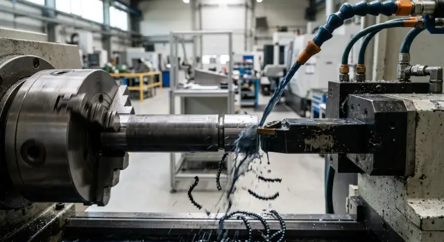
Grooving tool on a CNC lathe without jamming and chipping
Grooving on a CNC lathe needs the right insert, coolant delivery and pass sequence. We cover settings and common mistakes to avoid jamming and chipping.
Why the groove jams and inserts chip
When the cutter enters a narrow groove, the chips have no room. They can't leave the cutting zone fast enough, rub on the walls and build up in front of the cutting edge. At that moment cutting quickly turns into plowing.
The load on the insert rises in shocks. The edge no longer cuts smoothly but receives short impacts from the front and the side. That's how chips appear, especially on corners.
Usually there's more than one cause. Most often several factors coincide: chips pack in, the coolant doesn't reach the groove bottom, the tool holder vibrates slightly. After that the clean cut disappears, the workpiece shows rubbing marks, and the insert begins to break up.
Coolant is often overestimated in this operation. If the jet misses the cutting zone or loses pressure, it cools the top of the tool but not the groove bottom. That area heats fastest. Chips become sticky, the metal adheres to the edge more, and the problem grows quickly. This is especially obvious on ductile materials.
Another common source of trouble is excessive tool overhang. The farther the tool is extended from the turret, the easier it is for fine vibration to occur. At first it's almost inaudible, but the edge is already working unevenly. That's enough to get both galling and chipping.
The worst-case scenario is when everything lines up in one pass: deep engagement, poor chip evacuation, weak coolant supply and long overhang. The operator usually notices this by sound. The cutter seems to "drag" the part, cutting becomes heavy, and then the insert loses its edge. If you stop at the first sign, the tool and the workpiece surface can often be saved.
What to check before the first cut
Most problems start before the cycle begins. If the drawing calls for one groove width, but the insert cuts slightly narrower or wider, you'll soon get extra friction, poor chip flow and edge chipping. So start by checking three things: the actual groove width, its depth and the tolerance. Don't rely on a single marking on the box. It's easier to measure the insert once and confirm it fits the job.
Grooving is very sensitive to rigidity. If the part is clamped weakly, it will deflect in the first millimeters of cutting. This is especially noticeable on long blanks, thin-walled sleeves and parts with large overhang from the chuck. Before the first cut check clamp length, runout and whether the tailstock or a steady rest is needed.
The tool holder itself causes many problems. Excessive overhang reduces stiffness and the tool starts to shake under load. The groove becomes ragged and the insert quickly chips on the corner. Extend the holder only as much as needed for access. Removing even 10–15 mm of overhang usually calms the cut.
A common coolant mistake is simple: the nozzle points roughly at the tool but doesn't hit the cutting zone. Then the fluid cools the holder, not the contact between the insert and the metal. Before starting, check that the jet aims directly into the groove and helps wash the chips out.
Before the trial pass answer a few quick questions: does the insert match the drawing, is the workpiece clamped rigidly, is the holder overhanging too much, and does the coolant hit where the edge works? This check takes minutes but often saves the tool, the part and setup time.
How to choose insert width and shape
Mistakes often start before choosing the cutting parameters — at the moment someone puts the first available insert into the holder. A too-wide insert creates extra load. A too-narrow insert alters size and forces extra passes.
For narrow grooves it's usually better to take the minimum required width. That makes the cut easier, gives chips a better escape route and extends edge life. But setting an insert exactly equal to the finished width is not always wise. If the material is ductile or the groove is deep, it's safer to rough with a narrower insert then finish the width with a side pass.
Simple example: you need a 4 mm groove in steel that produces long chips. A 4 mm insert may work, but the jamming risk is higher. In many cases it's calmer to start with 3 mm, open the bottom, clear chips and then reach the final size.
Insert shape also greatly affects results. Look not only at width but at the chipbreaker. For ductile materials a sharper geometry often works better: it breaks chips earlier and doesn't press them into the groove. If the chipbreaker is too "blunt", the chip rubs on the groove walls and drags the insert.
The nose radius rule is simple. A larger radius makes the edge stronger but increases cutting forces. In a narrow or deep groove this is often unnecessary. A small radius cuts easier and reduces the risk of corner chipping on entry, though it may wear faster.
Choose the insert grade for the workpiece material, not by habit. For regular steels a universal grade with good chipping resistance is common. For stainless steel you usually need a sharper geometry and a grade less prone to built-up edge. For cast iron choose more wear-resistant grades. For aluminum a very sharp insert with a clean cutting edge works best.
If you hesitate between two options, it's often better to take the slightly narrower insert with more stable chip flow. One extra pass is usually cheaper than constantly replacing chipped inserts.
How to set parameters without extra risk
In grooving mistakes are more often made at the start than on the main cut. The first millimeters of engagement impose the greatest load on the insert, so reduce feed on entry compared to the working value. Often reducing feed by 15–30% for the initial engagement, then increasing to the main feed after a stable entry, is enough.
If the tool immediately receives full feed the edge takes a hit. From that come chipping, size drift and a rough groove bottom. Rushing here rarely pays off.
Cutting speed is also often treated in the wrong place. When chips form long ribbons, raising speed usually makes things worse. The chips heat more, smear and clog the groove.
Listen carefully during the first 2–3 mm. A calm, even sound usually means the tool entered correctly. If you hear squeal, vibration or short impacts, adjust the regime immediately before the edge starts to break.
Simple indicators:
- short, brittle chips — the regime is close to correct;
- long ribbon chips — don't rush to increase speed;
- blue, overheated chips — cutting is too aggressive or coolant is insufficient;
- torn chips with impacts — feed on entry is too high or tool is unstable.
Change one parameter at a time. Start with feed, then speed. Otherwise it's hard to know what helped. If chips behave poorly, make small steps: slightly reduce speed or slightly increase feed if the insert geometry should break chips better and the machine holds the load.
Insert width also directly affects safe parameters. The wider the insert, the higher the cutting force and the more cautious the entry must be. What works on a narrow groove often ends in chipping on a wide one.
In the shop, watch not the number in the table but three signs: sound, chip shape and the mark on the sidewalls. If any of them raises concern, the regime already needs adjustment.
How to deliver coolant into the cutting zone
If the jet misses the groove, the metal overheats too quickly. Chips soften, stretch and rub on the groove walls. That causes jamming and initial chipping even when the regime looks calm.
Coolant must hit the point where the cutting edge enters the metal. Feeding from above and slightly forward along the cut usually works best. Then the flow passes between the chip and the insert, cools the edge and helps chips exit the groove.
A wide spray is almost always worse than a precise jet. It wets the machine but doesn't solve the cutting-zone problem. You need a steady stream without strong dispersion. If the nozzle can be moved, bring it closer and check that the holder doesn't block it when the tool goes deeper.
Pouring coolant over the part hoping to cool everything is almost useless. The part surface will be cooler, but inside the groove the edge and chips will still overheat.
On ductile metals even correct coolant delivery can be insufficient. Stainless steel, mild carbon steel and similar materials often produce long, stringy chips. It's cheaper to stop briefly and clear them than to wait for them to break themselves. A short pause usually costs less than a new insert and a spoiled part.
Before a run do a quick check:
- turn coolant on before engagement and see where the jet actually hits;
- make a short trial pass at small depth;
- stop and check whether chips stick in the groove;
- adjust the nozzle if the flow hits the face of the part or the holder.
A typical shop picture is: the first parts come out OK, then inserts start chipping. Often the issue isn't the insert or the regime but the nozzle aimed too high. From outside the flow looks fine, but deep in the groove there's almost no coolant. Lower the jet a few millimeters and aim slightly forward and the cut runs smoother.
If groove stability is a problem, check coolant delivery early. You’ll see the difference in sound and chips: with accurate coolant the cut is quieter, there's less smoke, and the groove walls come out cleaner.
Sequence of passes for a stable groove
Edges often break not from one big mistake but from the wrong sequence of moves. If you rush to full depth the chip jams, the tool rubs on the sides and the insert quickly chips.
Start with a trial entry at shallow depth. This first cut immediately shows how the material behaves, how chips break and whether the insert drifts. An extra 10 seconds at the start usually pays off.
Then deepen the groove with short passes. Even if the metal seems soft, taking the full depth in one go is risky. Stepwise engagement keeps the load on the edge more even and chips exit easier.
After each deeper pass it's useful to retract the tool a little. In a narrow groove chips need a chance to leave the cutting zone. A small pull-out often helps more than just reducing feed to the minimum.
A common working scheme looks like this:
- first entry at small depth;
- several short cuts with the same step;
- a small retraction after each step;
- finishing pass at reduced feed;
- for wide grooves cut the center first, then finish the walls.
Leave the finishing pass for last and run it at reduced feed. Roughing cuts remove most material; the final cut removes marks, evens the bottom and gives cleaner walls. If you do it the other way around, the finished surface will be ruined on the next deepening.
Don't take a wide groove to size in one go either. First cut the central part to open room for chips, then finish the sidewalls. The tool rubs less on the sides and geometry is easier to hold.
A simple shop example
On a CNC lathe they were machining a shaft from stainless steel. The drawing called for a 3 mm wide groove and 6 mm deep. The first millimeters were calm, but around mid-depth chips stopped exiting freely and began jamming in the groove.
The operator noticed by sound and by marks on the part. The cutter started rubbing the sidewalls, the groove floor showed ripples, and the insert's edge developed small chips. Size could still be held, but quality fell fast.
The cause wasn't the insert itself. Its width was correct, but the coolant jet missed the cutting zone and failed to wash chips from the narrow groove. When chips accumulated at the bottom the cutter no longer cut cleanly but partially plowed and rubbed the metal.
The operator made two changes: redirected the coolant jet closer to the cutting edge and added a short intermediate retraction after several millimeters of engagement. The return into the cut was made smooth, avoiding a secondary impact.
After that chips began to leave much cleaner. They no longer packed into a tight lump but exited in portions. Even with the same geometry the process ran smoother.
The most noticeable effect came from the intermediate retraction. At about half depth the cutter briefly pulled back, chips were discharged, coolant had time to wash the groove, and the next pass went calmer. Many operators in this situation just reduce feed, but that doesn't always help. Stainless steel likes clingy chips, and too slow a cut often increases friction.
In the end the edge lasted longer and the groove floor became cleaner and smoother. This case shows a simple thing: problems rarely come from a single mistake. Usually it's a chain of small causes, and you must break that chain step by step.
Errors that quickly ruin the result
If the groove starts OK but on the third or fifth part you see galling, the issue is usually not the material. More often repeated small oversights are to blame: chips pack in, the insert overheats, the edge dulls and then chips.
One frequent error is a too-wide insert for a deep narrow groove. At first this seems more rigid and reliable. In practice the insert removes extra volume, chips have no room, sidewalls rub and cutting becomes heavy.
Another typical error is a large feed immediately after touching the part. At that moment the tool hasn't entered a stable cut. If you suddenly apply load the edge receives an impact, especially on hard material or with some runout.
A deep single pass instead of several short ones is also a poor choice. When the tool goes to full depth at once, both heating and cutting forces increase. Chips evacuate worse and the chance of jamming rises sharply. Several short passes usually give a cleaner floor and fewer chips.
One innocent-looking mistake is when the operator checks size on the first parts and calms down. Wear begins before size goes out of tolerance. If the sound sharpens, the groove floor dulls, or chips go ragged, inspect the insert.
Warning signs:
- chips form a lump and don't break;
- streaks appear on the groove floor;
- the tool cuts heavier than on the first part;
- a high-pitched squeal or sharp noise is heard;
- small chips are visible on the edge.
The most expensive habit is finishing "one more part" with a dull edge. That false economy almost always costs more than the insert itself because it ruins size, surface and the rhythm of the run.
Quick checklist before a run
Before starting a batch spend a few minutes checking. When a groove works on the edge, small things quickly turn into scrap: friction rises, chips jam, and the insert soon chips.
Check insert width against the actual groove and allowance. See where the coolant hits during a dry approach. Make sure the part is clamped rigidly with no noticeable runout, especially if the groove is near the overhang. Set feed on entry lower than on the main pass. And decide in advance by which signs you'll change the insert, without waiting for a clear chip.
A short trial run before a series shows more than a cutting table. If chips come out long and dark and the groove sounds heavy, stop immediately and fix feed, coolant or insert width.
What to do next on your shop floor
Start not with a batch but with one trial groove on a real part or a blank from the same lot. It's the fastest way to see where the regime holds and where risk begins: chips stretch, the insert squeals or the groove floor darkens.
Record more than RPM and feed. Also note practical things: tool overhang, insert width, depth per pass, coolant direction and material grade. Without these data it's hard to repeat a good result even on the same machine.
A simple scheme:
- make one trial groove at the base regime;
- after 3–5 parts compare chips and sound;
- inspect the groove floor and sidewalls;
- examine the insert edge under magnification;
- record the regime that yielded a clean result without chipping.
Don't look only at size. A good setup shows itself by several signs: predictable chip flow, no torn marks on the floor, no corner crumbling, and stable spindle load. If everything looks fine at first but by the fifth or sixth part the insert starts breaking, the issue is often not the insert but repeatability of conditions.
When a machine can't hold the regime, check the mechanics first. Play in joints, weak clamping, excessive holder overhang and poor coolant delivery quickly ruin even a carefully chosen setup. Often a simple check helps: reduce overhang, ensure steady coolant flow right into the cutting zone and repeat the same trial.
If you have several machines, don't transfer parameters blindly. One center may groove calmly while the same settings on another cause chip jamming. Differences usually come down to rigidity, chuck condition or actual coolant pressure.
If problems repeat regularly, it's sometimes useful to analyse the task with equipment specialists. EAST CNC works in Kazakhstan supplying CNC turning machines for metalworking, helping with selection, commissioning and service. This is helpful when you need to understand whether the issue is parameters, tooling or the machine's limits.
FAQ
Why does the groove start to jam right on entry?
Usually several factors combine: chips can't exit, coolant doesn't reach the groove bottom, and the tool vibrates because of excessive overhang. Reduce feed on entry, check coolant direction, and reduce the tool overhang by a few millimeters.
How can I tell from the chips that the cutting regime is wrong?
Look at chip shape and color. Short, brittle chips usually mean the cut is stable. A long ribbon, blue (overheated) color, or torn chips indicate overheating, poor evacuation, or too aggressive entry.
What insert width should I use for a narrow groove?
For a narrow groove, choose the minimum required insert width. That eases cutting and chip flow and reduces load on the cutting edge. With ductile material or deep grooves, rough first with a narrower insert, then finalize the width with a side pass.
When is it better to make the groove in several passes?
If the groove is deep, narrow, or the material produces long chips, don't take the full depth in one pass. Short steps with small retractions let chips escape and keep the cutting load even.
What should I change first: feed or cutting speed?
Start by adjusting the feed, especially on entry. Feed most often causes impact on the cutting edge in the first millimeters. Change speed afterwards and do it in small increments so you can see the effect.
Where should I direct coolant when grooving?
The coolant must hit the contact point between the insert and the metal, not just wet the part or the holder. Feeding from above and slightly forward along the cut usually works best. A wide spray rarely helps.
How much does excessive tool overhang matter?
Quite a lot. Excessive tool overhang reduces rigidity and allows fine vibration. The cutting edge then chips at the corners. If you can reduce overhang by 10–15 mm, the cut often becomes noticeably more stable.
How do I know it's time to change the insert?
Don't wait for clear dimensional failure. If the sound sharpens, the groove floor shows streaks, chips form into lumps, or a small nick appears on the edge, replace the insert. Trying to finish more parts with a dull edge usually costs more.
Why does a wide insert often cause chipping?
A wide insert removes more metal per pass and increases cutting forces. In a deep, narrow groove the chips have less room, rub on the sidewalls and pull on the edge. That leads to jamming and chipping faster.
What should I check before starting a series?
Before a series, check insert width relative to the groove and allowance, coolant direction during a dry approach, workpiece clamping rigidity and runout, and tool overhang. Do a short trial cut and listen: if the sound is heavy or chips come out poorly, correct settings immediately.