Grooving for a Retaining Ring Without Scrap in a Narrow Groove
Grooving a retaining ring seat requires the right tool width, radius control, and a proper finishing pass; otherwise a narrow groove can ruin the whole batch.
Why a narrow groove can ruin a batch
In a narrow groove, an error of a few hundredths is already enough to change how the retaining ring works. It is not enough to hit the diameter alone. You have to hold the width, the shape of the side walls, and the radius at the bottom. Otherwise the ring will not sit the way the drawing intended.
The problem is usually simple, and that is what makes it especially annoying: the machine repeats the same mistake on every part. If the setter left an extra 0.02 mm in offset, chose a tool that was a little too wide, or did not account for edge wear, the defect will run through the whole batch. On the first part, you may not notice it. By the thirtieth, it is clear the scrap is not random.
A retaining ring groove leaves almost no room for rough correction. If the groove is narrower than spec, the ring will not go in all the way or will fit with too much interference. If the groove is wider than spec, the ring sits too loosely, shifts, and holds axial load worse. The second case is usually worse: the extra material is already removed, and you cannot put metal back.
After the finishing pass, there is often nothing left to fix. The tool has formed the final width and radius, and the room for adjustment is gone. If the radius at the bottom came out larger than needed, the ring may sit deeper or work unstably. A simple tweak does not help here.
On the shop floor, this feels frustrating. The shaft diameter is within tolerance, the program runs smoothly, there are no alarms, and yet the batch fails assembly because of one groove. That is why a narrow groove should not be treated as a minor operation. Very often it is the detail that decides whether the part moves forward or ends up in the scrap box.
What to check before the first part
Even a good cutting mode will not save a batch if basic checks are skipped at the start. With this kind of operation, the error appears before the first cut.
First, check the drawing. What matters is not only the groove width and depth, but also the bottom shape, the transition radius, and the tolerance on the side walls. This is often read too loosely. If the drawing calls for a radius, a flat bottom is not acceptable. If the width is tightly specified, you cannot assume the finishing pass will bring the groove into tolerance on its own.
Then check the workholding. Runout immediately eats up the allowance, especially in a narrow groove where the tool has almost no room for extra stock removal. If the workpiece runs out, one wall will come out cleaner than the other, and the width will drift even with the correct program. Also check the tool overhang. Too much overhang causes deflection, chatter, and a torn surface.
Inspect the insert separately. It is better to do this before the first part, not after the first surprise on inspection. Even a small chip on the cutting edge changes the picture: the size may look almost right, but the bottom comes out with burrs and one of the walls shifts.
Another common mistake is a bad touch-off. If the tool is set against scale, a dirty face, or a trace from a previous operation, the zero is already wrong. After that, the operator starts chasing the size with offsets, even though the error began right at the start.
Before starting, a short check is enough:
- verify the groove width, depth, and bottom shape against the drawing;
- check workpiece runout in the setup;
- make sure tool overhang is minimal;
- inspect the insert for chips and wear;
- set touch-off only on a clean surface.
Only then should you make a trial cut outside the batch. It is better to sacrifice one blank or one area of allowance than to go back and rework the whole lot.
How to choose the tool width
The mistake often starts not on the finishing pass, but when the tool is selected. If you take a tool that matches the nominal groove width exactly, you leave almost no room to correct anything. For grooving a retaining ring seat, that is a poor choice.
In practice, it is safer to choose a tool that is slightly narrower than the required groove. Then the rough cut forms the groove, and the finishing pass brings it to size without extra side-wall removal. For a 2.0 mm groove, many shops first try a 1.8 or 1.9 mm tool instead of installing a 2.0 mm one just because that is what is written on the insert.
The marking is only useful at the beginning. The real cutting width is always checked on the part. It depends on tool height, runout, holder rigidity, feed, and the condition of the edge after the first cuts. Sometimes it is very simple: the insert is marked as 2.0 mm, but in reality it cuts 2.03 mm. For a wide groove, that may be acceptable. For a retaining ring groove, the batch can be stopped on the first ten parts.
If the batch is long, edge wear has to be considered from the start. A new tool rarely ruins the size on the first part, but after 30-50 parts the cutting width can drift by several hundredths. That is enough for the ring to stop fitting correctly or sit too loosely.
That is why it is better not to rely on one tool without a trial check. It is much safer to run a short sample, measure the actual groove width, and only then release the batch. If the machine and part allow it, it helps to keep a second tool of the same type on hand, already checked for its actual cutting width. In a shop, that small detail often saves a shift.
How to keep the bottom radius under control
The width may pass, and the part still may not assemble. The reason is often the bottom radius. In a narrow groove, this is common, because there is almost no allowance for shape errors.
First, compare the drawing with the insert profile. If the drawing calls for one radius and the insert forms another, the machine will not correct that through feed rate or offsets. Before starting, it helps to look not only at the catalog but also at the actual mark on a trial part.
Also check the transition from the wall to the bottom. A worn or unsuitable cutting edge often leaves not a smooth radius, but an almost sharp corner. It is easy to miss by eye, especially after a light finishing pass. In assembly, that defect shows up right away.
How you measure the first part matters too. If one time you check the radius with a template and the next time you only judge the width with calipers, those are two different checks. That kind of confusion pushes the setup in the wrong direction, and the groove shape starts to vary from part to part.
It helps to separate two errors: one for width and one for radius. They often show up together, but the causes are different. Width drifts because of tool position, wear, and extra side stock removal. Radius drifts because of the insert profile, edge condition, and entry path.
If the shape changes, do not start changing every offset at once. That is one of the most common mistakes. The operator changes X, then Z, then feed, then depth, and two parts later no one knows what actually helped. It is better to change one parameter at a time and immediately look at the tool mark on the new part.
How to make the finishing pass without removing too much
In a narrow groove, scrap is often caused not by the tool itself, but by the wrong order of passes. When the operator tries to finish the bottom and both walls almost in one go, the tool gets squeezed, the edge heats up, and the width drifts in the last hundredths.
Start by removing the main stock with roughing cuts. It is better to make two calm passes than one aggressive one. For a retaining ring groove, a small allowance is usually left both on the bottom and on the walls for finishing. If you leave stock on only one side, the groove center shifts, and then you have to chase the size manually.
After roughing, bring the groove bottom in first. That locks in the depth and removes one variable from the setup. After the bottom pass, do not leave the tool at the bottom any longer than necessary. Even a short pause can leave a mark or remove extra stock.
Then finish the first wall. Usually it is the side that is easier to measure from and use as a reference. It is better to check right after that, not only at the end of the part. With a tight tolerance, that short stop saves the batch.
Only then finish the second wall. Do not try to remove the rest in one hard move. It is safer to take a small cut and, if needed, make a light repeat pass with the same tool, without changing overhang or making more corrections. That repeat often relieves the tool spring and evens out the surface.
The simple rule here is: the narrower the groove, the calmer the finishing should be. If the groove is 2 mm wide, an extra 0.02 mm can already ruin the ring fit.
An example from the shop
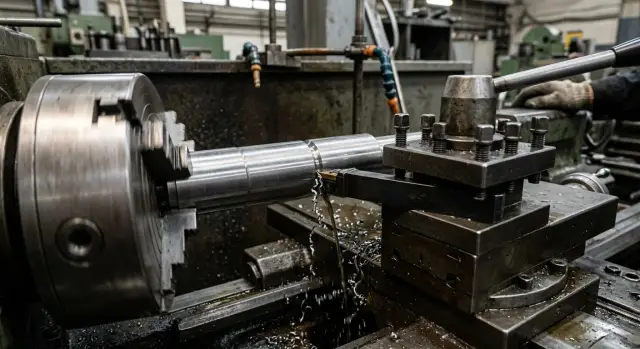
In one production job, a groove for a retaining ring was turned on a 35 mm shaft made of steel 45. The drawing called for an external groove 1.80 ±0.02 mm wide with a small corner radius. The batch was ordinary for the shop: 120 parts, with no time for a long changeover.
At first, the operator installed a 1.8 mm grooving tool and went almost straight to final size in one plunge. On the first two parts, everything looked fine: 1.81 and 1.82 mm. On the fourth part, the width had already moved to 1.84 mm, and a few parts later it reached 1.86 mm.
The reason was simple. The tool was "on size" only on paper, while in real cutting the narrow groove did not forgive either the extra edge radius or the repeated contact with the side walls. When the edge wore in slightly, the tool started rubbing the sides more strongly. The operator added short finishing touches to clean up the mark, and in doing so widened the groove himself.
After the batch was stopped, the tool was replaced with a 1.6 mm one with a smaller corner radius. The size was then achieved not by the tool width itself, but by the sequence of passes. First came a rough plunge with a small allowance on the walls and bottom. Then one wall was brought in, then the bottom, and only at the end the second wall was finished in one pass, without back cuts.
That approach immediately stabilized the size. The next ten parts came out at 1.80-1.81 mm, with no spread at the tolerance limits. The ring seated properly, with no tight fit and no looseness.
The full release still was not given until the first five parts after the tool change were checked. They looked at width, depth, corner radius, burrs on the edge, and the actual ring fit. It took about 15 minutes, but the risk of scrap across a hundred shafts was gone.
Where mistakes happen most often
Scrap rarely comes from one big reason. Usually a batch is ruined by several small decisions that seem harmless on their own.
The first common mistake is trying to hit the full width in one pass, right to size. On paper, that looks fast. On the machine, the tool deflects a little, chips push to one side, and the groove goes oversize or gets a torn wall. It is much calmer to leave a small allowance and remove it in the finishing pass.
The second mistake is rushing the corrections. The operator sees a deviation and immediately adjusts both X and Z. After that, it is no longer clear what actually caused the scrap: depth, wall position, tool width, or play in the clamping. If you change one axis at a time, the cause stays visible.
The third mistake is checking only the width. After the first part, many people look at one number and relax. That is not enough. You need to check the tool edge, the bottom shape, and the wall condition. In a narrow groove, even a small chip quickly changes both the cutting width and the groove geometry.
Another common slip is measuring a hot part. The metal has not cooled yet, and the operator is already using a micrometer or gauge. The size seems fine, then the part cools and the number changes. After that, offsets are adjusted for no real reason, and the process drifts even further.
And finally, the program is often changed too early. If the size only drifts after several parts, the problem may not be the path at all, but heat, edge wear, clamping, or repeatability. Sometimes the program has nothing to do with it.
A quick check before starting the batch
Before a run, it is worth spending 10 minutes on a short check. In a narrow groove, the error rarely comes alone: if the actual tool width is off, the radius does not match, and the order of passes keeps changing during the job, the batch quickly drifts away from the drawing.
The minimum checks are:
- make a trial cut and measure the actual groove width;
- immediately compare the bottom radius with the drawing;
- write down the pass order in the operation sheet;
- do not measure the first part while it is still hot;
- limit the number of corrections for the batch in advance.
Usually, the second and fourth items are the ones that get skipped most often. People still check the width, but they treat the radius as a minor detail. Then the ring fits too tightly, or on the contrary, rattles. The same goes for a hot first part: the measurement gives a false feeling that the size is already right.
The operation sheet is better kept short. It is enough to note how much stock to leave for the semi-finishing pass, when to make the finishing cut on the groove, and when to measure width and depth. If the sequence is not written down, two operators on the same program can easily get different results.
The rule for corrections is simple: small adjustments are fine, a chain of corrections during the batch is not. If the size still drifts after an agreed correction, the cause should be searched for in the tool, clamping, heat, or cutting mode.
What to do if the size will not hold
If the groove size keeps changing, do not change everything at once. Otherwise the cause will hide, and the scrap will come back on the next part. Go in order: machine, tool, clamping, mode.
First, gather the base data. You need the drawing, the material, the blank diameter, the overhang length, the batch size, and the dimensions of the first parts. Without that, the analysis quickly turns into guesswork.
It helps to record not just one measurement, but at least the first 5-10 parts. Look not only at the final groove width, but also at the radius, depth, and axial position. A repeated fault almost always leaves a clear trace: the size starts drifting after warm-up, changes every other part, or steadily shifts to one side.
It is convenient to check in this order:
- machine: axial play, chuck runout, return repeatability, and heat buildup in the first minutes of work;
- tool: actual width, edge wear, chip damage, and the real radius at the tip;
- clamping: clamping force, part overhang, stop, and the stability of the blank seat;
- mode: feed, spindle speed, depth of the last pass, and the pause before measuring.
A simple table often helps. Write down the part number, machining time, dimensions, and what was changed after each measurement. In 15 minutes, you can see more than after a long argument at the machine.
A typical case looks like this: the first three parts are in tolerance, then the groove width drifts 0.03 mm undersize. The operator blames the material, but the real cause is different: the grooving tool heats up quickly, and the finishing pass is run with the same feed as the roughing pass. After lowering the finishing feed and checking the actual tool width, the size holds again.
If this operation repeats month after month, it is worth looking not only at the current setup, but also at the machine itself. At that point, it may make sense to discuss the task with EAST CNC. The company works in Kazakhstan as the official representative of Taizhou Eastern CNC Technology Co., Ltd. and does not only supply CNC lathes, but also helps with selection, commissioning, and service. On east-cnc.kz there is also a blog with practical metalworking materials, which is useful for comparing approaches to jobs like this.
When the size will not hold, there is almost never one single "main" cause. Usually it is a combination: a slightly worn tool and an aggressive mode, a normal mode and weak clamping, a correct program and a poor touch-off reference. If you check these points one by one and record the result, the batch becomes predictable again.