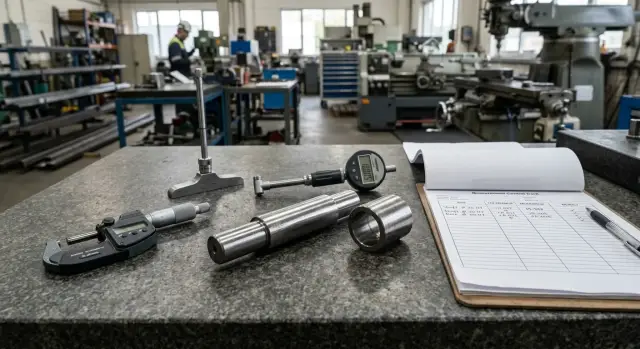
Gauge, Micrometer, and Bore Gauge for Parts Flow in the Workshop
A gauge, micrometer, and bore gauge are chosen based on size, tolerance, and inspection frequency. Let’s look at a simple combination of measuring tools for a parts flow.
Why one tool is not enough
In a workshop, one tool almost never covers all inspection, even if the parts seem simple. Checking speed and measuring accuracy rarely live well in the same instrument. When the flow keeps moving without pauses, the operator needs to quickly separate good parts from bad ones. When the size is close to a tolerance limit, you need a tool that shows the exact number.
A go/no-go gauge solves the first task. It quickly divides parts into good and bad and does not waste time reading hundredths. For a batch of identical shafts or bushings, this is often the fastest way to inspect them: each check takes only seconds.
But a gauge does not show the actual size. With it, you cannot tell whether the part sits in the middle of the tolerance band or is already close to the limit. That is what a micrometer is for. It helps you see the actual outside size, monitor tool wear, and spot process drift before rejects appear.
The same logic applies to holes. A micrometer works well for outside diameters, while a bore gauge is needed for a hole or a bore. Otherwise, proper control of the internal size is impossible. This is especially noticeable on bushings, housings, and parts after boring, where the count is not only in millimeters, but also in hundredths.
The choice also depends a lot on the pace of the station. If one part is checked per hour, you can spend more time on precise measurement. If batch after batch comes through the station, slow inspection becomes a problem itself. People start measuring less often, skipping intermediate checks, or using one tool where it is simply inconvenient.
That is why a gauge, micrometer, and bore gauge usually work together. The gauge keeps the pace, the micrometer shows the real outside size, and the bore gauge checks holes. This combination fits a live parts flow better than trying to solve everything with one tool.
Where to start
You should start not with a list of tools, but with the part itself. Otherwise it is easy to buy a convenient tool that does not hold the required tolerance or slows work at the machine.
First, look at the nominal size on the drawing — without rounding or guessing. A size of 25 mm and 25.00 mm can lead to different tool choices if the tolerances are different.
Then assess the tolerance itself. It shows how precise the part inspection must be. If a shaft has a narrow tolerance zone, a caliper is no longer enough, even for a small size. If the tolerance is wider, quick pass/fail inspection is often more practical than measuring every value in detail.
The next step is to separate outside and inside dimensions. For a shaft, journal, or outside diameter, a gauge or micrometer is usually suitable. For a hole, the logic is different: a bore gauge or limit gauge is needed, depending on the task. This is where people often make mistakes: they choose a tool by size range instead of by the type of surface.
Before production starts, it is helpful to answer a few simple questions: what nominal size is on the drawing, what tolerance is listed next to it, where is the dimension located — outside or inside the part, how often will it be checked, and who will do it — the operator at the machine or a separate inspector.
The last points change the choice more than it seems. If the operator checks the size every 10–15 minutes, they need a fast and easy-to-understand tool. If the measurement is done by an inspector in a separate area, you can use a tool that works more slowly but gives an exact numeric result.
On a turning line, this becomes obvious right away. A batch of bushings with frequent hole checks calls for one approach, while infrequent checks of outside diameter in a small series call for another. Once the starting data are collected, the tool combination can be chosen calmly: by size, tolerance, and inspection frequency.
Where a gauge saves time
A gauge is useful wherever you need to answer the same question again and again: is the size within tolerance or not? If the parts flow is steady and the operation repeats hundreds of times per shift, a gauge is almost always faster than a micrometer or bore gauge.
On a turning line, this is especially noticeable in serial machining of shafts, bushings, and seating surfaces. The operator does not need to find the number every time, compare it with the tolerance band, and decide whether the part can move on. They simply check the go and no-go sides and make the decision immediately.
That is the whole point of a gauge. It does not show the actual size, but it removes unnecessary actions. For a production flow, that is a plus: fewer pauses, less manual routine, fewer mistakes when reading the result.
A gauge is easiest to use in four cases:
- when identical parts are checked frequently;
- when you need a quick yes-or-no answer;
- when inspection is located right at the machine;
- when each check only has a few seconds.
On a batch of 300 identical bushings, the difference shows up quickly. With a micrometer, the operator spends time setting up, applying pressure, reading, and recording. With a gauge, the check takes just a couple of motions. Over a long run, that is not a small detail but a noticeable loss of time every hour.
But a gauge has its limits. If you need to know how far the size has shifted toward the upper or lower tolerance limit, a gauge alone is not enough. It handles quick sorting, while a precise tool is needed to set the machine and find the cause of rejects.
Before starting a batch, the gauge itself should be checked for wear. A worn working surface can easily create a false sense of order: the part passes inspection, but the fit does not assemble properly later. Another common mistake is choosing a convenient gauge that only seems to match the size. The go and no-go sides must match the actual tolerance band on the drawing, not just "almost fit."
If the flow is stable and the decision on the part is made immediately, the gauge should be kept right where the operator works. Then it is not a formality, but the fastest filter on the station.
How to choose between a micrometer and a bore gauge
A micrometer and a bore gauge solve different tasks. A micrometer is used for outside dimensions: shaft diameter, collar thickness, wall thickness, or width between faces. A bore gauge is needed for inside dimensions — holes, bushings, and bores.
If a part looks like a shaft or pin, a micrometer is usually the first choice. It quickly gives a clear outside size and works well for repeated inspection. If it is a bushing, housing, or block with a seating hole, it is much harder to get an accurate picture without a bore gauge.
Price alone does not decide much. First, look at the measuring range. For shafts from 18–25 mm, a 0–25 mm micrometer will do. For holes from 50–160 mm, you need a bore gauge with the right range, not just the cheaper tool.
You also need to check the scale division and accuracy for your tolerance. If the tolerance on the size is 0.02 mm, a tool with a 0.01 mm step already gives too rough a picture. You will see the number, but you will not understand how close the part is to reject.
There is another practical point: access to the measuring zone. A smooth outside diameter is easy for a micrometer. But near a shoulder, groove, or short step, a regular micrometer can be awkward and give a poor reading. Holes are similar: a bore gauge works well for long bores, but in a short hole or right at the edge it becomes harder to use.
If you need to check your choice quickly, ask yourself four questions: where is the size located, what range do you need, how narrow is the tolerance, and can you reach the measuring zone without misalignment?
The workshop logic here is simple. For a batch of shafts, people choose a micrometer because it quickly shows the outside size. For bushings and seating holes, they choose a bore gauge because it measures the inside diameter in place and helps reveal taper or out-of-roundness. If a part has both critical sizes, one tool is usually not enough.
How to build a working combination
An inspection set is best built not from a catalog, but from the most sensitive dimension of the part. First, choose the tool that gives an exact number where you cannot afford to miss. For outside diameters, that is usually a micrometer; for holes, a bore gauge.
Then decide whether a gauge is needed for quick go/no-go checking. If the batch runs continuously and the operator checks many parts per shift, a gauge usually pays off quickly. It does not replace precise measurement, but it removes unnecessary delays.
After that, check the range on the real part, not just on the drawing. If the shaft is 48 mm, a 25–50 mm micrometer will work, while a 50–75 mm one will not, even if the size is close. The same logic applies to a bore gauge: the working range must cover your size without stretching the tool.
Next, connect the combination to the operation itself. If a CNC lathe machines a shaft, the operator needs a clear step after roughing and another after finishing. If a bore is being machined in a bushing, the bore gauge should be right next to that operation, not in the next room with the inspector.
It is useful to set the inspection plan for the batch right away. The first part is usually measured with the full set: a precise tool and, if needed, a gauge. In the middle of the batch, a gauge and a spot check with the precise tool are often enough. At the end of the batch, it is better to measure again with the precise tool to make sure the size has not drifted because of tool wear or heating.
Simply put, a gauge, micrometer, and bore gauge are assigned based on three things: what size must be held, what tolerance is specified, and how often that size is checked.
How to account for inspection frequency
Inspection frequency changes the choice of tool more than people usually think. The same size can be checked in different ways, but in full inspection speed comes first, while in sample inspection a clear numeric result matters more.
If every part is measured, the operator cannot be burdened with a long chain of steps. In that mode, a gauge works best: apply it, check it, move on. It does not overload the person with extra numbers and does not slow the flow.
A micrometer and a bore gauge are more accurate, but in high-volume work they often lose on speed.
With sample inspection, the picture changes. When every tenth part or the first part after adjustment is checked, it is better to use a tool that shows the actual size. Then you can see where the process is drifting — toward the upper tolerance limit or the lower one. That helps spot a problem earlier.
If the operator measures right at the machine, it is better to reduce the number of motions. The fewer times they pick up the part, move the tool, and search for the right point, the smoother the work goes. That is why the full set of tools is rarely needed at one station at the same time. Usually one fast tool is enough for current checks and one precise tool is enough for scheduled verification.
When a part is taken to an inspection station, you need to consider not only the measurement itself, but also the path to the station, the queue, and the part temperature. A hot part straight from machining can easily show extra microns. If you measure it immediately, you may get a size that will change again in a few minutes. Here you do not need a complicated procedure, just a simple rule: how long the part must rest before inspection and who is responsible for that.
For small batches, a large set of tools is often unnecessary. If the batch is small, changeovers are frequent, and the dimensions are simple, extra tools only create confusion. In that case, it is better to choose one main tool for the tolerance and one backup tool for disputed cases.
A practical scheme usually looks like this: every part is checked in the fastest possible way, the first part and the part after adjustment are measured with a tool that gives a numeric result, a disputed size is rechecked with a more precise tool, and hot parts are not measured immediately after machining.
Example for a batch of shafts and bushings
Imagine a batch of two parts: a 25 mm shaft and a bushing with a bored hole for it. If the shaft tolerance is narrow, quick inspection alone is not enough. In this case, a tool combination works better than relying on just one thing.
For a 25 mm shaft, a micrometer is used first. It shows the actual size, not just "go" or "no-go." This is useful at the start of a batch and after any adjustment. If the shaft must stay within a few hundredths, the micrometer immediately shows which way the size has moved.
To avoid spending time on every part, a snap gauge is placed nearby. The operator quickly checks acceptability right at the machine. The micrometer stays for the first part, periodic rechecks, and questionable cases. This approach usually saves time and helps prevent size drift from being missed.
A bushing after boring is more conveniently checked with a bore gauge. For a hole, it is more useful than a micrometer because it shows the internal size at the measuring point. If the hole starts drifting into taper or out-of-roundness, the bore gauge will show that too.
In practice, the scheme is often simple: the first part is measured fully, the shaft is checked with a micrometer and a snap gauge, the hole in the bushing is checked with a bore gauge, and then the inspection interval is set, for example every fifth or tenth part.
The interval depends on machine behavior, tool wear, and batch size. If the size stays stable, you can measure less often. If the spread starts to increase, the inspection frequency should be raised immediately.
When the size begins to drift, do not blame the tool first. Check the machine setup, tool compensation, cutter condition, and measuring conditions first. Very often the cause is there.
Where people make mistakes most often
The most common mistake is trying to cover all inspection with one tool. It sounds convenient: buy a tool with a wide range and expect it to fit any part. In practice, this choice usually leads to more movements, slower checking, and more disputes at the tolerance limit.
A range that is too wide rarely helps in production. The tool takes longer to set, and it becomes harder to notice a small size drift. If a station works steadily with one group of sizes, it is better to choose a tool for that range, not one "for all cases."
The second mistake is confusing quick sorting with precise measurement. A gauge is good where you need to quickly decide whether a part is good or bad and keep production moving. But it does not show the actual size. If the process drifts toward the upper or lower limit, the gauge will not explain that.
A micrometer and a bore gauge solve a different task. They are needed when you want to see the number, understand the direction of size drift, and adjust the process in time. If every part is measured only with a micrometer, inspection will slow production down. If everything is checked with just one gauge, the drift may be noticed too late.
Another common mistake is related to temperature. The part comes off the machine and is measured immediately. Warm metal can easily add extra hundredths, especially with tight tolerances. In the end, the operator thinks the size has already drifted, when the reason is only the part condition. One rule helps here: either wait before measuring, or always measure under the same conditions.
Many people lose accuracy even earlier — they do not check zero before a shift or a new batch. That takes less than a minute, but later you do not have to untangle a dispute over dozens of parts.
Another frequent issue is mixing up the approach to a shaft and to a hole. The drawing may show similar dimensions, but the inspection is different. A shaft is easy to track with a micrometer or a gauge for outside dimensions. A hole cannot be fully checked the same way: it usually needs a bore gauge or a pass-through gauge.
A simple sign of the right choice is this: the operator immediately understands what they are doing at that point in the process. Either they quickly reject the part, or they take a precise size for adjustment. When those tasks are mixed together, the station almost always loses both time and quality.
Pre-start checklist
Before the first part, it is better to spend a few minutes preparing than to sort the batch again later. This is especially noticeable in production flow: one missed detail quickly turns into dozens of questionable parts.
A proper inspection plan starts with simple things:
- write the size, tolerance, and acceptable range in the work card instead of leaving everything only on the drawing;
- assign the main tool for each size and separately define the verification tool;
- specify the inspection frequency without vague wording like "as needed";
- check zero and remove worn gauges from service.
In a metalworking station, this looks very down to earth. For a bushing, the operator first checks the bore gauge against a master, then measures the first part, and then runs the flow according to the set inspection plan. For a shaft, the order may be different: the first part and every twentieth part are checked with a micrometer, and between them a gauge is used if the task allows it.
If such a checklist hangs right by the machine, startup goes more calmly. People spend less time on unnecessary measurements and notice faster when the size starts to drift.
What to do next on the shop floor
The main thing is to turn all this into a working routine instead of keeping it in your head. Every size should have its own tool, its own inspection frequency, and a clear place in the control route.
Usually a simple table is enough for this: size and tolerance, measuring point on the part, required tool, inspection frequency, and who is responsible for the result. After that, it becomes immediately clear which sizes require full inspection and which can be checked by sampling.
Full and sample inspection should be separated from the start. The wording "check periodically" only creates confusion. It is much more useful to write it clearly: first part, then every tenth part, after insert change, after changeover, and at the end of the batch.
Then the scheme should be tested on one real batch. Usually within the first few hours you can already see where measurement is awkward, which size takes too much time, and where the inspection interval can be reviewed without losing quality.
If the workshop is launching a new CNC lathe or an automated line, inspection should be agreed on at the equipment selection stage. Otherwise the machine is already in place, the program is ready, and the measuring points and inspection order do not match the real work. At that point, the experience of a supplier who understands the process itself is useful. EAST CNC supplies CNC lathes for metalworking, helps with selection, commissioning, and service, so the measuring plan can be linked to the future launch in advance.
A good result for the shift is simple: every size has its own tool, its own inspection interval, and a clear rule for use. If that is missing, mistakes start not in measurement, but much earlier — in unclear control organization.
FAQ
Can one tool cover all inspection?
No, in a production flow one tool almost always loses. A go/no-go gauge quickly rejects bad parts, a micrometer shows the outer size in numbers, and a bore gauge checks holes. If you try to cover everything with one tool, inspection becomes slower and less precise.
When is a gauge really needed?
Use a gauge when you need a fast answer to one question: is the part within tolerance or not? It is especially handy at the machine when the operator checks many identical parts and only has a few seconds for each check.
When should you use a micrometer?
A micrometer is used for outside dimensions when you need to see the actual number. It helps catch size drift before rejects appear and keeps the setup under control at the start of a batch, after adjustment, and in questionable cases.
When is a bore gauge necessary?
For holes, bushings, and bores, use a bore gauge. It shows the internal size at the measuring point and helps reveal taper or out-of-roundness that you would not see with a quick pass/fail check.
How do you choose a tool for a tolerance?
Look not only at the size, but also at the tolerance. If the tolerance band is narrow, a caliper or a coarse tool is no longer enough. A good rule is simple: the tool should clearly show whether the size is inside tolerance, not just give an approximate number.
What should you choose for 100% and sample inspection?
If you measure every part, speed should come first and a gauge should be close at hand. If you inspect by sampling, use a tool that gives a numeric result so you can see which way the process is drifting.
How often should you check the size in a batch?
Usually the first part and the part after adjustment are measured with a precise tool. After that, the interval depends on the process behavior: for example every fifth, tenth, or twentieth part. If the size starts to wander, increase the inspection frequency right away.
Can you measure a hot part?
Right after machining, it is better not to measure if the part is still warm. Metal can add extra hundredths, and you will get a false result. The simplest approach is to set one waiting period before measurement and keep the conditions the same for the whole batch.
What should you check before starting a batch?
Before starting, check zero, the gauge condition, the required measurement range, and the inspection plan itself. Before the first part, write down the size, tolerance, inspection frequency, and who measures it. Then there will be fewer disputes during the shift.
What combination works for shafts and bushings?
For shafts, people usually choose a micrometer and, if the flow is dense, add a snap gauge for quick checking. For bushings and seating holes, they use a bore gauge. This combination covers both speed and accurate checking without extra movements.