Forged Gearbox Housings: How to Keep Allowance
Forged gearbox housings need precise allowance and stable datums. We cover setup order, stock zones, common mistakes, and quick checks.
Why the housing shifts after roughing
A housing made from a forging blank does not change shape "by itself." The metal already came into the shop with internal stresses from forging and cooling. While the outer layer is intact, the part holds that load inside. As soon as roughing removes part of the metal, the balance changes and the housing can bend slightly.
This becomes especially noticeable when the roughing allowance is removed unevenly. One side loses a lot, the other keeps a massive section, and the blank starts pulling toward the stiffer area. By eye, this can be almost invisible. But on the next setup you can already see that the face has "moved" and the holes or seats have shifted by fractions of a millimeter.
With gearbox housings from forgings, this happens often because of the part geometry itself. A housing usually has feet, flanges, windows, and bearing bosses. The cross-section is different everywhere. A thick zone holds, while a thin wall or a long foot reacts first.
Weak datums make the problem worse. If the first setup is done on rough cast or forged surfaces with scale, draft, and local waviness, the part sits in one position on the machine. After roughing, that same surface is no longer a reliable support, and on the second setup the housing sits differently. That is where the misalignment between setups comes from.
Clamping is its own story. Thin walls can flex even under normal force. While the housing is clamped, everything seems straight. Release the clamp, and the part springs back. In the end, the machine machined one geometry, and after removal the part on the table has already become slightly different.
A simple example: on a housing, a large amount is first removed from a flange and one side wall in roughing, while the part is located by unmachined feet. After repositioning, it turns out that the boring axis has shifted relative to the split face. The reason is not one operator mistake, but a combination of factors: stresses in the forging, uneven metal removal, weak datums, and clamping deformation.
To put it plainly, roughing is not just removing excess metal. It is the stage where the forging machining route either keeps the geometry stable or starts shaking it loose.
What to check in the forging before the first setup
A forging for a gearbox housing should not be put on the machine "as is." First, you need to understand where there is extra metal and where it is already tight. Otherwise, after roughing one side will sag and you will get misalignment between setups.
Start with a simple comparison of the actual contour against the drawing. Look not only at the overall size, but also at the shape of individual zones: feet, flanges, bosses, and datum pads. Forgings often have drafts, local bulges, and parting-line shifts, which can make the part look symmetrical from the outside while the allowance on each side is already different.
It helps to go over the part with a marker and immediately mark the places where the shape deviates most from the drawing. The usual trouble spots are along the die parting line, near thickness transitions, and in corners where the metal flows less well. If the parting line is shifted, one half of the housing may have extra metal, while the other is already close to size before machining.
Check thin-wall zones separately. On gearbox housings, these are often cavity walls, areas near ribs, and places close to large openings. If you remove too much too early, the wall releases internal stress and the part will move after the first setup.
Before choosing the first datum, measure the metal allowance on the exact faces you plan to build the route from. The datum face should do two things: give a secure clamp and leave enough allowance to correct the geometry later. If the pad is already almost to size or runs on a draft, it will not make a good datum.
At the first inspection, it is usually worth marking four things:
- where the contour is closest to the final size;
- where the parting line runs and how far it is shifted;
- which walls and shelves are thinnest;
- where there is enough metal for support and clamping.
After that, it is already clear what to use as the first setup reference. For example, on a housing with feet and a flange, it is often wiser to clamp not on the flange, but on the thicker outer pads on the body if the flange allowance varies. The first clamp must hold the part firmly, not just conveniently.
If the allowance at the datum areas is questionable, it is better to spend time on layout and measurements now. That is cheaper than chasing alignment errors later and rebuilding the forging machining route from scratch.
Where to leave allowance and where to remove it earlier
If you remove metal where the housing will later support itself and be located, the part loses rigidity too early. After that, the forging can easily twist after the first roughing pass. That is why on support feet, the flange, and the pads that will become future datums, it is better to keep extra stock longer than on secondary outer walls.
With forged gearbox housings, one common mistake is trying to bring future datums almost to size right at the start. It looks convenient, but later the part sits on faces that have already shifted themselves. It is much safer to first remove the main excess metal from the body mass and only finish the datum faces later, when the part shape is already closer to working condition.
For paired sides, there is a simple rule: if you remove a lot from one side, remove a similar amount from the other side in the same stage. This applies to the left and right wall, the upper and lower face, two feet, and symmetric bosses. When roughing goes "to one side only," internal stresses immediately pull the housing, and misalignment between setups is almost inevitable.
You should also not rush cavities. Opening them early is useful only in the thickest areas, where the extra mass clearly holds stress. But if you open a large internal cavity along its full length right away, the housing quickly becomes softer, and the feet and flange start behaving on their own. Then even careful repositioning will not save the geometry.
Special attention should be paid to accurate holes, especially if they will later hold bearing seats. Around such places, you need even stock around the circumference and along the length. If you leave a lot on one side and almost finish the other side, the boring operation will later try to correct the tilt of the metal instead of relying on machine accuracy.
A practical shop-floor sequence is:
- first remove excess metal from the outer body without bringing future datums close to size;
- then machine paired sides with roughly equal stock removal;
- after that, partially open the thick internal zones;
- next, bring the foot and flange faces close to semi-finish condition;
- keep accurate holes and final datums closer to the end.
A small example: on a housing with a flange and two feet, it is better to lighten the thick side wall and boss early, but keep the feet "heavy." The flange should also not be thinned across the whole area too soon. Then on the next setup the housing will sit predictably instead of showing a new twist after every cut.
In short, keep allowance where the part supports itself, where you will still build datums, and where the final geometry will appear later. Remove metal earlier from zones that do not set location and do not weaken the housing after the very first pass.
How to choose datums between setups
Between setups, it is usually not the machine that moves the housing, but a weak datum. If the part sits differently each time, roughing quickly turns into a chase for twist and extra stock.
For a forged gearbox housing, you first need one honest support face. It should be made on the most stable area, where the part sits securely and the clamp does not bend the wall. Often this is the future mounting face or a separate pad for it, if there is enough stock there. There is no need to remove metal until a perfectly "pretty" spot is achieved. It is enough to get a reliable support without rocking.
After that, a second datum is set at a right angle to the first. Usually this is a side pad, an end face, or a prepared wall that is easy to read with a feeler and indicator. Using a raw forging draft as a datum is a bad idea. It has scale, local sag, and shape variation. On the first setup that may seem minor, but after repositioning it will cause noticeable axis drift.
A good between-setup datum scheme looks like this:
- the first face holds the part without rocking;
- the second face provides a clear right angle;
- both datums are located closer to the rigid part of the housing;
- the datum areas are left untouched until roughing is finished.
The last point is often ignored. The operator cleans up the datum pad too early, then flips the part and rests it on a surface that has already shifted after stress relief. For forged gearbox housings, this is a common cause of movement between setups.
It is better to leave a small stock allowance on the datums and finish them later, once the main pockets, windows, and outer contour have already been rough machined. Then the housing datums stay alive throughout the rough cycle and give the same seating on every setup.
After each repositioning, it is worth checking repeatability before cutting. Three simple actions are enough: seat the part, indicate the first face, then the second, and compare one control dimension to an already machined feature. If the numbers are already drifting at this stage, the part will move even more later.
Put very simply, a datum should be machined, rigid, and still alive until the end of roughing. Everything else usually brings surprises.
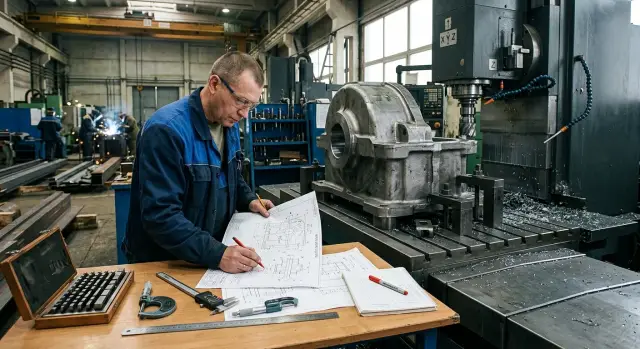
Step-by-step operation sequence
With a forged gearbox housing, the part usually shifts not because of one mistake, but because finish work starts too early. If too much metal is removed in the very first setup, the housing loses rigidity, internal stresses come out unevenly, and after repositioning the datums no longer behave the same. For forged housings, it is safer to move from rigidity rather than from the desire to reach size faster.
First, remove the scale and prepare the places where the part will sit and be clamped without rocking. There is no need to clean the whole forging at once. It is enough to create a few solid support pads and remove irregularities where the clamp actually works. If the clamp goes onto a raw, uneven surface, the housing already sits with a twist from the start.
Next, make the first rough datum face. It is better to choose it on the massive area of the housing, not on a thin flange or foot. This face is not for appearance or final size. It is needed so the next setup rests on metal in a predictable way. That is why stock is left on it.
After that, machine the opposite side. Again, there is no need to go to final size. The goal is simpler: get a pair of rough but understandable surfaces so the housing can already be set up between them without surprises.
This sequence usually works best:
- prepare the surfaces for the first clamp and remove forging scale where the part supports itself;
- make the rough datum face with stock left on it;
- flip the part and machine the opposite side, also leaving stock;
- rough out the windows and pockets, but do not finish thin walls or fully close the corners;
- let the part cool, check for movement, and only then bring in the finishing datums and holes.
When opening windows and pockets, do not lighten one side of the housing too aggressively right away. If one side is already hollow and the other still carries thick metal, the part can twist easily. It is better to remove metal more evenly, in several passes, and keep material near the ribs, flanges, and bearing lands.
After heavy roughing, the housing should be allowed to cool to shop temperature. Do not measure a hot part too early. Set it on supports, check the plane with an indicator, look at the diagonals, and observe the flange behavior. If movement has already appeared, it can still be caught before finishing.
Finishing datums, bearing bores, and holes should be done only after this pause. The worst thing is trying to save one setup and go straight to size. That is usually what creates the misalignment that later takes a long time to find.
Example route for a housing with a flange and feet
A housing with a flange and feet often comes from stamping or forging in less-than-perfect shape. The most common picture is a shifted forging parting line, with one foot sitting slightly higher than the other. If you go straight to finish faces and bearing seats, the housing will almost certainly shift between setups.
The working route is usually built more carefully. On the first setup, the part is positioned so the support remains rigid even with a crooked forging. Only the lower pad and two stops are brought into the cut, so the setup can be repeated later. The lower face is brought close to clean condition, but without excessive stock removal. The two stops are made on adjacent surfaces so the housing does not wander in X and Y later.
After that, the housing is turned over and placed on the finished lower pad and two stops. On the second setup, the top face is machined, but not to final size. It is better to leave a small stock allowance. For this kind of housing, that is often safer than chasing the size immediately. If the metal releases internal stress after roughing, you still have room to correct it.
Then a pause helps. Sometimes a couple of hours are enough; sometimes the part is left until the next shift. After the pause, check the flatness of the lower and upper surfaces, then look at the shift of the future seat axis relative to the chosen datums. That is where you can see whether the housing has settled or moved.
If everything stays within tolerance, only then do you move on to boring the bearing seats. It is better to do this in one setup from already verified datums. That reduces the risk of bore misalignment and tilt relative to the flange.
A convenient sequence looks like this:
- receive the forging and check the twist along the die parting line;
- on the first setup, bring the lower pad and two stops into shape;
- on the second setup, machine the top face with stock left on it;
- let the part cool and remeasure flatness and shift;
- after checking, bore the bearing seats.
In this route, allowance works like insurance. It gives you a chance to correct the geometry before machining the most sensitive areas. For a gearbox housing, that is usually cheaper than later chasing the cause of noise, heat, and early bearing wear.
Mistakes that cause misalignment
A gearbox housing rarely ends up twisted "by itself." Usually the route causes it: one extra metal removal, a poor clamp, or a datum change without rechecking dimensions. For forged housings, this is especially noticeable because the forging already carries internal stresses, and roughing only releases them.
A common mistake is to remove almost all of the stock from one side in a single setup. After that, the part is no longer balanced: one wall is already thin, while the other still holds stock. After repositioning, the housing can move slightly, and the hole axes no longer match what you expected. In practice, it is better to remove metal more evenly, even if that adds one extra pass.
Boring accurate holes too early is also a bad idea. After heavy roughing, the housing can still change shape, especially if massive areas, feet, or a flange remain nearby. If the finish size is made too early, the next setup often turns a precise hole into scrap. The part needs time to settle into its shape after the main material removal, and only then should you move to the accurate features.
Another issue is clamping on a thin flange. The machine will faithfully run the program, but the part itself is already springing under the jaws or hold-downs. While the housing is clamped, everything looks normal. As soon as you remove it, the face shifts and the alignment drifts. If the housing has massive feet, ribs, or a more rigid rough datum, it is better to hold it there.
Where geometry is most often damaged
- They change the datum scheme between setups and do not recalculate dimensions from the new datum.
- They use the old route dimensions, even though the first machined face has already moved.
- They skip measurement after heavy roughing to "save time."
- They check only one dimension, while the drift is usually visible in two or three linked points.
Changing datums without recalculation is especially unpleasant. For example, the first setup was done from a cast or forged surface, and the second from a machined face. If the process engineer does not recalculate the chain of dimensions, the machinist gets a formally correct program and the wrong part.
After heavy roughing, a short control check is needed. It is enough to verify the support face, the vertical shift, and the position of the future hole relative to the datum. These few minutes often save an entire batch. Losing one measurement is cheaper than chasing misalignment in finishing.
Quick checks after each setup
After removing the part, do not rush straight to the next setup. Spend 2-3 minutes on inspection, because with forged gearbox housings the twist often starts with a small shift that first seems trivial.
The most convenient approach is to keep a short measurement sheet by the machine and record the actual numbers after each operation. Memory can fail, but a record immediately shows where the part started to move.
- First, check whether there is enough metal for the next setup. If the roughing allowance on one side is already small, the next clamp will seat the housing differently than planned.
- Then compare wall thickness in paired areas: near the feet, along the sides of the opening, and near the flange. When one side has noticeably more stock than the other, rigidity is already different and the part bends under clamping.
- Quickly check the axis position relative to the datum faces. You do not need a long inspection: an indicator or height gauge will immediately show whether the axis shifted after turning the part.
- Look at the clamp itself. If the part is held only with extra shims, thin spacers, or some random "help" from the setup kit, the datum is already questionable.
- After heavy roughing, let the part cool and check the deflection again. On a warm forging, the face often looks fine, but after 10-15 minutes it shows a different size.
If one of the points fails, it is better to stop right away. Otherwise, you will carry the mistake forward and later start looking for the cause in the tool, the program, or the machine, even though the problem started on the previous setup.
A good rule of thumb is simple: after each cut, you should know three things - how much allowance is left, where your real datum is, and whether the axis position has changed. This short control catches misalignment between setups before finishing operations, when fixing it is already expensive and slow.
What to do next on your shop floor
If forged gearbox housings sometimes move after roughing, there is no need to tear up the whole route immediately. First, lock in a few simple rules in the process sheet so the process engineer, setup technician, and operator all work to the same scheme.
On the operation sheet, mark not only the gearbox housing datums, but also the areas where metal must remain until the next setup. This is especially important where there are thin feet, flanges, or long walls. When stock-retention zones are not clearly shown in the forging machining route, every shift handles the part differently, and misalignment between setups appears very quickly.
Also add a mandatory measurement after the heaviest roughing stage. Do not postpone this check. Immediately verify the support face, datum positions, thickness in weak areas, and how the housing changed after the main metal removal. This check often takes 5-10 minutes, but it shows earlier than anything else where the part starts to drift.
Usually five actions are enough on the shop floor:
- mark the working datums and the surfaces that must not be touched too early in the route;
- specify where to leave stock after roughing until the next setup;
- review the clamping scheme for thin flanges and feet so the clamp does not bend the housing;
- check whether the machine has enough axis travel, tool reach, and rigidity for this forging;
- make the post-heavy-roughing measurement a mandatory operation, not just a verbal suggestion.
If you are choosing equipment for such parts, look at more than just the table size in the brochure. You need extra travel, proper access to difficult areas, and stable performance in heavy roughing. EAST CNC helps with machine selection, supply, commissioning, and service when you need to assess the task as a whole, not just compare catalog models.
Start with one typical housing and make these changes to the route. After two or three repeats, it is usually already clear at which step the drift appears and where the scheme needs improvement.