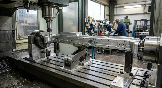
Fold-away support for a long housing component in a fixture
A fold-away support for a long housing component helps remove sag directly in the fixture, reduce the weight of the setup, and shorten setup time.
Why a long part sags downward
A long housing component starts to sag under its own weight even before the first pass. The greater the length and the thinner the walls, the more noticeable the deflection becomes. On a table or in a vise, you can see it right away: the edges sit on the supports, while the middle drops slightly.
At first glance, this often seems minor. In machining, that "minor" issue quickly turns into a size error. The machine does not cut the ideal geometry, but the part that has already deformed in the setup. If the center sags, the tool removes one layer in the middle and a different one near the edges. After the clamp is released, the part partially springs back and the size starts to drift.
This is easiest to see on long datum surfaces, fits, and holes where a straight line is needed along the entire length. The size may stay within tolerance at the edges, but in the middle you get a dip or extra stock.
A regular clamp without support does not solve the problem. Jaws, hold-downs, and stops pull the part to the datums, but they do not remove the sag between support points. If the housing is not very rigid to begin with, clamping can even add distortion.
Then the familiar process starts: the operator adds shims, loosens and tightens the clamp again, moves the stops by fractions of a millimeter, makes a test cut, and measures once more. One setup can easily take an extra 20-40 minutes, and the process still is not stable.
The most annoying part is that the error is hidden. The first part may come out acceptable, while the second and third do not. Each blank sits in the fixture a little differently, and the spread only becomes obvious after a few parts.
If the middle is cutting differently from the edges, first check the setup itself, not the tool or the program. In many cases, a support in the fixture helps more than yet another clamp adjustment. It supports the part exactly where it loses stiffness.
When a support is built into the fixture
A built-in support is needed when the part starts to "move on its own" as soon as it is set up. The edges sit on the datums, the clamps work normally, and the middle still sags. Even a small deflection later shows up in the size.
Usually the problem is visible not at the edges, but between the clamping points. That is where the size starts to drift: a hole shifts in height, a machined surface loses its geometry, and repeatability from part to part drops. If this happens in the same zone every time, it is better to build the support point into the fixture.
This is especially useful when the part needs to be supported in the same place every time. The operator should not have to search for the support point by eye. They set the blank down, clamp it, bring up the support, and get the same setup as on the previous part.
A separate stand next to the machine may seem like the easy option, but in practice it often gets in the way. It has to be positioned on site, its height must be checked, and it must be watched so it is not moved. For a single part, that is still manageable. For a production run, that small detail quickly turns into wasted time and disputed measurements.
A heavy welded frame can also remove sag, but the price of that approach is simple: more weight, less convenience, and more difficult changeovers. If the problem is local, building a large structure just to support one point usually does not make sense.
In practice, a built-in support is used when the middle of the part clearly drops after setup, the size varies specifically in the middle of the span, an external support gets in the way of loading, and the contact point has to be repeated on every part without manual adjustment.
This is especially noticeable in production work. The part sits the same way every time, the operator spends less time on setup, and the machine gets a stable base for machining.
How a fold-away support works
A fold-away support holds the weak area of the part, but it does not replace the datums. That is the key principle. First the part is seated on the datums and clamped, and only then is the support brought to the area of sag.
If you do it the other way around, the support will start lifting the part. On the outside it may look flatter, but in fact the position is already distorted. After removal from the fixture, the size will shift.
The working sequence is usually simple:
- The operator loads the part while the support is retracted.
- The part is located and clamped.
- The support is brought up until it makes light contact with the weak area.
- After machining, the support is retracted and the part is removed.
When adjusted correctly, the support does not push the part upward and does not change the dimensional chain. It only removes sag under the part's own weight or under cutting load. This is especially noticeable on long housings, where one thin rib or wall can ruin the result along the entire length.
A well-made unit is almost invisible. It does not get in the way during loading, supports the right point during machining, and then moves aside or down again after the cycle. The operator can remove the part without going around the fixture and without a manual prop.
Why a built-in support is more convenient than an external structure
An external stand looks solid, but in everyday work it often creates extra hassle. It has to be brought to the machine, positioned, checked for height, and then checked again after the first part. Every time the setup changes, the process starts over.
A built-in support is already in the fixture. The setter does not have to look for it around the shop and adjust it again from scratch. That saves not only time but also nerves. The fewer manual actions before startup, the fewer accidental mistakes.
There is another advantage that is very noticeable in production: the support point does not wander. If the support is fixed in the fixture, it returns to the same place every time. That means the part sits the same way from batch to batch, and the result depends less on who set up the fixture and how accurately a temporary support was positioned.
A built-in scheme usually brings several practical benefits at once: less extra metal around the machine, faster setup, better tool access to the machining zone, and easier chip removal and setup monitoring for the operator.
External stands often block tool access. As a result, the path has to be changed, the tool overhang increased, or the operation moved. A built-in support is easier to place so it holds the part from below without entering the working area.
Chips are easier to deal with as well. Separate supports create pockets where fine chips and dirt collect. Then the support no longer seats properly, and the height shifts by fractions of a millimeter. If the unit is hidden in the fixture and folds away only when needed, it is easier to keep clean.
So a built-in support is convenient not because of complicated mechanics, but because it is useful in everyday work. Less hassle during setup, fewer accidental differences between installations, and a cleaner working zone.
How to build in the support step by step
It is better to start not with the unit drawing, but with the part itself. Place the blank as it will sit in operation and look for the longest span. That is usually where the sag is greatest.
It helps to run an indicator over several points and repeat the normal clamping force. Wherever the reading changes the most, that is where the support contact is needed. That is much more accurate than placing the support "roughly in the middle."
Choose a stiff area for the contact point. A rib, a thickened section, a boss, or an area near a wall will work. Do not bring the support under a thin wall: the wall will deform locally, and the lengthwise error will remain.
Then it is best to follow a simple order:
- Place the part on the datums and fully repeat the normal clamping.
- Bring the support to the chosen point and set its height from the datum or control dimension.
- Check the unit travel in two positions: during loading and in the working position.
- Run the tool path dry and make sure the tool, chuck, jaws, and chips do not hit the support.
- Make a test part and compare the size at the beginning, middle, and end of the length.
It is better to set the height with an adjustment screw, shims, or a stop with a clear scale. Adjusting it "by eye" almost always adds extra pressure. Then the support no longer supports the part; it bends it upward.
It is also worth checking how easy the part is to load. If the fold-away unit gets in the way of loading the blank or catches the edge, people on the shift will quickly start working around it. On paper the support exists, but in real work it stops being used.
During the test cut, look not only at the size but also at the contact mark. A dent, a shiny strip, or an unpleasant sound during the pass usually means two things: the contact point is wrong, or the support is set too high. Often a small correction is enough to noticeably reduce the spread along the length.
A simple shop-floor example
One shop was machining a housing about 980 mm long. The part was clamped at the edges because that made it easier to bring in the tool and keep a clear passage along the main surfaces.
At first everything looked fine. But in the middle of the housing the size started to drift: one run passed inspection easily, while another required a repeat check.
The reason was typical for parts like this. The edges held the housing rigidly, while the middle had no support and sagged under its own weight and the cutting force. Even a small deflection added extra tenths.
The operator tried the usual fixes: adding shims, checking the height, making a test pass, and measuring again. Every setup took another 20-30 minutes, and there was still no confidence in the result.
After that, a fold-away support was added to the fixture under the middle of the housing. It was placed where it did not interfere with clamping or block tool access to the machining zone. The sequence became simple: place the part on the datums, clamp it at the edges, bring the support up to the middle, and make a control pass.
After the modification, the housing stopped sagging in the center. The size along the length became more even, and the repeat check took minutes instead of half an hour. Most importantly, the operator no longer had to keep "catching" the part with shims.
This example shows the point of a built-in support very clearly. It does not make the fixture bulky, but it removes an error source where a regular clamp is no longer enough.
Common mistakes
Even a good support will not give results if it is placed in the wrong spot or used for the wrong purpose. Most often, the problem is not the unit itself, but how it is tied into the datums, tool access, and machine movement.
The most common mistake is simple: the support is brought under an area that cannot carry the load well on its own. If the pad presses on a thin cover, a weak wall, or a zone with cutouts and pockets, the part will not straighten; it will dent or shift sideways. The contact must be on a stiff area.
The second mistake is just as common. People try to use the support to lift the part into the correct position. That should not be done. The part position is set by the datums and clamps, while the support only removes sag. If it starts forming the housing position, the geometry is already off before the first pass.
Problems also appear with the size of the pad. A pad that is too large seems safe, but in practice it often blocks tool access. Then the path is changed, the tool is extended, or the operation is moved, even though the real reason is simply that the support was made too generous.
There is another nuisance as well. The unit was included, but its retraction was not thought through. On the dry run everything looks fine, but in the cycle the spindle, turret, or tool body passes too close. In a shop, that is a very expensive small mistake.
Finally, people often forget to lock the adjustment. The screw slips a little after several setups, the contact changes, and repeatability drops. From the outside it looks like "the machine is drifting," although the cause has long been in the fixture.
In short, check five things: the pad must touch a stiff area, the support must take load only after datuming, the pad size must not interfere with the tool, the retraction mechanism must fully clear the unit from the working zone, and the adjustment must be firmly locked after setup.
Quick check before startup
Before the first part, it is better to spend a few minutes checking than to search later for the cause of scrap in the program, the tool, or the clamp. With a built-in support, almost all problems show up right away: sticking, unwanted contact, wrong height, or a mark near the tool path.
You need to watch not only the unit itself, but also how it behaves in the cycle. Manually, everything may seem fine, but in the working stroke the part may already get an extra lift or, on the contrary, remain unsupported.
Before startup, it is enough to check the following:
- the support folds away freely and returns to the same point every time;
- the contact pad is free of chips, dirt, and burrs;
- the height matches the control setting;
- the tool passes the unit with clearance on all moves;
- the first part is measured not only at the edges but also in the center.
If something does not match, do not try to force the problem with the clamp. Tightening the part harder is the easiest fix, but it usually only hides the mistake for one operation. On the next pass, the size will drift again.
A good habit is simple: do the first check at a slow feed and without rushing. That way the operator can immediately see whether the tool hits the unit, whether the support stays partially open, and whether the part seat changes after clamping.
In practice, the setup looks very simple. Load the blank, close the clamp, raise the support, run a dry cycle, and measure the first part. If the center and edges hold size and the mechanism moves without force, the fixture is ready for production.
What to do next
If a long housing component sags, do not rush to rebuild the entire fixture. First separate the problem. Part sag and clamping error often look the same, even though the causes are different. Check the datums, reduce the influence of the clamp, and only then decide whether a built-in support is needed.
It is better not to test the idea on the whole batch right away. Take one part where the deviation is already visible and try a simple scheme with the support built into the fixture. A trial run like this quickly shows whether it helps hold the size or whether the cause is somewhere else: in the clamping point, overhang, or cutting parameters.
If the test works, record not only the idea itself but also the numbers. Write down the support height in the working position, the point when it is brought in or retracted, the loading and clamping sequence, and the control dimension after the first cut. Without that, even a good fixture will eventually start living by memory.
The machine and the fixture are best considered together. A rigid machine will not save a part that hangs without support. And a support alone will not fix a weak setup scheme.
If these tasks come up repeatedly on similar parts, it is worth discussing them not only with the fixture designer but also with the equipment supplier. EAST CNC, the official representative of Taizhou Eastern CNC Technology Co., Ltd. in Kazakhstan, works with CNC machines for metalworking, commissioning, and service. So in practice, you can review not just the machine and not just the fixture, but the whole machining scheme for a specific part. The company also publishes useful materials on such topics in its blog at east-cnc.kz.
The next step is usually the simplest one: make one trial, record the result, and check whether another setter can repeat the same scheme without extra explanations. If they can, the solution is already suitable for the shop.
FAQ
When is a fold-away support really needed?
Use a fold-away support when a long part visibly sags between clamping points and the size drifts in the middle. This is usually seen in a flat surface, a seat, or a hole: the edges look fine, but the center shows a dip or extra material. On a production run, the problem becomes more obvious because each blank sits a little differently. If the operator is already spending time on shims and repeated measurements, a support in the fixture usually gives better results.
How is a fold-away support better than a regular clamp?
A clamp holds the part by its datums, while the support only removes sag at the weak point. If the part is long and not very rigid, one clamp cannot hold the middle of the span. The right sequence is simple: first seat the part on the datums and clamp it, then bring the support up until it makes light contact. That way you do not change the part position or lift it upward.
Where is the best place for the support contact point?
Look for the spot where the part loses stiffness the most, not the geometric center. This is often the long span between supports, and it is best checked with an indicator under normal clamping force. Place the contact point on a stiff area: a rib, boss, thickened section, or an area near a wall. Do not place the pad under a thin wall, or you will dent the wall without fixing the lengthwise error.
Can the support itself spoil the size?
Yes, if the setter uses it like a jack instead of a support. When the support lifts the part into position or pushes too high, it changes the part location before the first cut. To avoid this, set the height with a screw, shims, or a stop with a clear adjustment. After adjustment, lock the unit immediately, or the contact point will start shifting from part to part.
Why is a built-in support more convenient than an external stand?
An external stand helps for one-off work, but on a production run it often takes time away. You have to bring it in, set the height, and make sure nobody moves it during the shift. A built-in support is already part of the fixture and returns to the same point every time. That makes the part repeatable and saves the setter from wasting minutes on manual adjustment.
How do you know the sag is the real cause?
First look at the pattern along the length of the part. If the edges hold size and the middle drifts, the cause is often the setup rather than the tool path or cutting insert. Make a test cut and measure the beginning, middle, and end. If the deviation repeats in one zone and changes from one setup to another, check the sag and the support scheme first.
How do you set the support height correctly?
Do not set the height by eye. Bring the support up to the clamped part and let it touch lightly without lifting the body. Then make a test part and compare the size at the edges and in the middle. If you see a pressure mark, a shiny line, or extra clamping force in the center, lower the support a little and check again.
What should be checked before the first part?
Before starting, make sure the unit folds away freely, returns to the same position, and does not interfere with the tool on any move. Then clean the contact pad of chips, dirt, and burrs. It is best to run the first part calmly and measure it immediately, not only at the edges but also in the middle. That way you quickly see whether the support holds the size in the working zone.
Won't the support get in the way of the tool and chips?
It can, if the designer leaves the pad too large or does not plan the retraction properly. Then the support blocks access, forces a tool path change, or collects chips around itself. This should be checked during the test run. Verify loading, the dry cycle, and the tool pass with clearance, and place the unit so it supports the part from below without entering the working zone.
Can this support be added without a full fixture redesign?
In most cases, yes. If the problem is local and the part sags only in one area, you do not need a heavy frame around the entire fixture. Usually one unit with clear adjustment and proper retraction is enough. Start with a test part, record the support height and the setup order, then check whether another setter can repeat the same scheme without extra explanations.