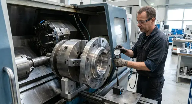
Fixturing Large Flanges on a Lathe Without Excess Runout
Fixturing large flanges on a lathe: how to choose a clamping scheme, check supports and set up monitoring so a heavy part doesn’t introduce extra runout.
Why runout grows quickly on a large flange
On a large flange, small issues become visible very quickly. A tiny chuck error looks insignificant, but on an 800–1000 mm diameter an indicator already shows a noticeable spread. So the cause is usually not one big mistake, but several small displacements that add up into an unpleasant runout.
The first cause is the part's own weight. If the flange is supported unevenly or supports are in the wrong places, the metal will sag slightly even before cutting starts. The larger the diameter and the thinner the section, the more this becomes apparent.
The second cause is clamping. On a massive hub the jaws rarely deform the part significantly, but a thin rim is easily pulled out of position. With heavy tightening the part changes shape, and after cutting starts the readings are no longer the same as during setup.
The third cause is a poor base. Dings, scale, saw marks after cutting or worn surfaces change the contact area with each new clamp. Formally the part is placed in the same chuck, but in fact it seats on different points.
On a large diameter even a small tilt quickly magnifies. If the face is off by a few hundredths at the base, on the outer edge this turns into noticeable axial runout. The same goes for radial runout: a small axis shift on a large flange looks like a serious error.
Therefore you cannot mount a large flange like a regular washer. If the support and clamping scheme doesn’t match the part’s shape, runout will appear before the first pass.
What to check before mounting the part
A good setup starts with measurements, not with the chuck. First understand what you are putting on the machine and how the part will behave under its own weight.
Immediately check the outside diameter, the mass and the overhang after mounting. Mass is needed not only for safe clamping. It shows the load the chuck, spindle and supports will receive. Overhang also strongly affects the result: the same flange behaves differently when mounted short and when it has a large overhang.
Then determine the working datum. Most often this is the face and the seating diameter, but on a repair part they are often worn or damaged. If the face has dings and the diameter is oval, you won’t get an accurate setup even on a good machine.
Also look at the wall thickness in the clamping area. A thin section under a jaw easily moves inward by a few hundredths. On a large diameter that’s enough to cause noticeable axial or radial runout. In such parts an support ring often helps: it preserves shape and reduces local bending.
Check the machine beforehand as well. Quickly inspect the chuck and jaw seating surfaces to ensure there is no dirt, steps or obvious wear, then check spindle runout on a mandrel or test shaft. Also check if the jaws have enough travel for a normal and safe clamp.
Indicator, mandrel and support ring of the correct size should be at hand before work begins. When one of these is missing, operators usually try to regain accuracy by repositioning and extra tightening. With a heavy flange that almost always ends in lost geometry.
How to choose a fixturing scheme
Choose the fixturing scheme by the logic of the drawing, not by how easy it is to clamp the part. If a dimension is taken from the face and the axis of a hole, those surfaces should define the setup. Otherwise the error in the datum will propagate through the whole machining.
From which surface to reference
First identify the primary surface for the part. If you need concentricity between the OD and a central bore, don’t build the setup from a random outer crest. If you must control axial runout, support the face that will be used for subsequent dimensions.
Mixing rough and finish datums in one setup rarely works. A common mistake: the part is first located by a cast or cut outer contour and then expected to be accurate relative to a machined bore. In that case each datum pulls the part in its own direction and runout grows even with careful clamping.
On thin flanges one radial clamp is usually not enough. Jaws hold the part but the disc can bend, especially with a large diameter. In this scheme it’s better to add a face support: a full ring, support pads or a flat backing plate under the working face. Then the jaws fix position while the support prevents the part from turning into a screw.
For a heavy part also consider the moment from the mass. The farther the center of gravity from the clamping plane, the more the flange pulls down. A short overhang and support on a larger diameter often give the biggest improvement. If you hold the part only by a narrow band, the mass will itself start to shift the axis.
If the datum is still rough
A rough surface rarely suits precise location. Casting skin, scale, dings and waviness on the face give a false contact. In such cases first remove a small locating allowance from the future datum, and only then use it as a working datum. Sometimes a light skim on the face and the datum band makes the next setup much calmer.
A useful rule: one fixturing scheme should hold the geometry you will later control. If the scheme doesn’t match the drawing’s logic, you can clamp the part very hard but it won’t get any truer.
How to choose clamping without bending the part
The error often starts in the chuck. If jaws pull a flange by a thin rim, the metal springs and the part already stands distorted. From the outside it may look fine, but after the first pass the face and OD start to wander.
When possible, clamp through a stiffer zone. If the flange has a massive hub or a thick seating area, bear on that, not on the thin edge. When such a zone is absent, a ring or spacer helps. They spread the force wider and prevent the jaws from punching one narrow area.
On large flanges soft jaws usually work more calmly than universal jaws. They are bored to the actual diameter of the part, so contact is tight and even along the arc. This is especially noticeable where the wall is uneven and a standard jaw loads the metal too locally.
A large overhang from the chuck also quickly adds problems. The part starts acting like a lever: even moderate tightening bends the edge more, and cutting then amplifies the error. Keep the flange closer to the chuck when possible and don’t leave unnecessary length.
Bending is often visible by the part’s behavior. After tightening readings on the face change, the OD moves more than expected, and after loosening the runout becomes different. Often the first light cut removes metal unevenly around the circumference. That’s a good signal: the problem is not the cutting mode but the clamping scheme itself.
A practical routine: first locate the part with light contact. Then tighten the jaws to working condition and recheck the face and diameter with an indicator. On a large flange the final draw-in often changes the picture more than it seems.
Mounting and alignment procedure
Before mounting, clean all surfaces involved in seating: the datum, jaws, the part’s face, supports and seating places. A small chip under the face on a heavy flange sometimes causes more runout than a light clamp. If the edge has a burr or dent, remove it beforehand, otherwise the indicator will show a false picture.
Set the heavy part down on the support gently and without tilt. If you bring the flange to the jaws with a crane, don’t let its own weight pull it into the jaws. First seat the part on the support, check that the face lies flat, and only then bring the jaws up.
Clamp in steps. First the jaws only touch the part and fix its position. After that tighten them gradually and with equal force. On a large diameter an extra turn on one jaw quickly shifts the size and adds runout.
Then check two parameters. Measure radial runout on the OD or on the surface from which you will machine. Check axial runout on the face. Rotate the spindle slowly and by hand. This makes it easier to tell a real seating error from a local nick or dirt.
If the face reads poorly while the diameter still holds, the part usually hasn’t sat on the entire face. In that case slightly loosen the clamp, correct the seating and repeat the measurement. If the face is already straight but the OD drifts, correct the jaws with small adjustments. On a heavy part abrupt corrections almost always make things worse.
When both readings are within limits, check the part again after the final tightening. Sometimes the last draw-in shifts the flange by a few hundredths. Before starting, rotate the spindle by hand to ensure the part doesn’t rub anywhere and the support doesn’t interfere with the cutter path.
How to monitor runout during machining
On a heavy flange runout rarely stays the same from setup to finish. Metal is removed unevenly, the part heats up, jaws change the contact area, and the datum can move after the first minutes of cutting. So control is part of the process, not a one-time measurement at the start.
When to measure
The first check is needed before the first pass. If the indicator already shows excess deviation, it’s too early to cut and you must correct the seating.
The next measurement is after roughing. It’s at this stage that extra runout often appears: the flange has released internal stresses, jaws have shifted slightly, and readings changed. If the face was 0.03 mm before cutting and became 0.08 mm after the rough cut, it’s better to catch the problem immediately rather than hope the finish pass will fix it.
Before finishing, repeat the same measurements in the same places with the same indicator. Otherwise the comparison loses meaning. If the machine was stopped for a long time and the part heated or cooled significantly, a short repeat check is also worthwhile.
In practice a simple rhythm is enough: check face and diameter before the first pass, repeat the same checks after roughing, and check them again before finishing.
What to watch besides the indicator
Watch the temperature of the part and the jaws. On a large flange temperature differences cause noticeable shifts, especially with large roughing cuts. Visual assessment is hard, so use the size behavior and how readings change after a pause.
If the jaws heat more than the part, clamping force is no longer what it was during alignment. At that point it’s easy to make a mistake: see runout, tighten jaws further and cause bending instead of fixing the issue. First find the cause, then change the clamp.
It’s useful to record each measurement in a setup log. A short table is enough: time, operation, face, diameter and notes on heating. After a few runs it becomes clear when runout starts to grow. For repeat parts this saves a lot of time.
Common mistakes when working with a heavy flange
Rarely is runout caused by a single reason. Errors usually combine. The operator over-tightened the jaws a bit, left too much overhang and checked the part with an indicator only in one area. Individually these things sometimes pass. Together they almost always cause drift after the first passes.
One of the most common mistakes is clamping on an unmachined edge hoping for an accurate seat. After cutting or casting the edge often has local bumps, scale and unevenness. The flange seats in the chuck not by its geometry but by random contact points.
Too strong clamping causes no fewer problems. With a heavy part there’s always a temptation to pull it tighter than needed, especially on a large diameter. But a thin rim can bend slightly before machining. Then people look for causes in the chuck, tool or program, although the problem was created by the clamping.
A long overhang without support is also dangerous. Even a stiff flange can sag slightly under its own weight, especially when held by a narrow zone. When the cutter removes allowance, the load changes and indicator readings drift. In that case a steadying device like a steady rest, support or a different setup scheme usually helps more than endless re-adjustment.
Measurement mistakes are common too. If you control runout only at one point, you can miss a tilt of the face or a shift of the OD. It’s more reliable to check at least the face, the seating and the outer surface. Then you see where the size moves.
Another frequent error is not re-checking the part after roughing. Smooth chips don’t mean the fixturing held. After the first cut a heavy blank can shift a bit in the jaws or release internal stress. A couple of minutes for a repeat check often saves the whole operation.
Shop example: large-diameter flange
The difference is clear in a simple example. A blank arrived about 900 mm in diameter and nearly 180 kg in weight. The face after cutting was uneven: a noticeable step remained at the edge and there was waviness in places. Mounting such a part immediately on the finish clamp was risky.
If in that situation you pull the blank into the jaws and try to fix runout by fiddling, you’ll spend a lot of time and still get unstable results. So the operator used a two-step setup.
First the part was placed in a rough clamp with moderate force and a small pass was taken on the face just to get a flat support plane. After that the flange was re-located to the new datum and clamped in soft jaws bored to the actual diameter.
The difference was noticeable. After the first clamp axial runout was about 0.35 mm. After re-seating on a clean face and correct contact in the soft jaws it dropped to roughly 0.08–0.10 mm.
Work then proceeded more calmly: no long corrections before each pass and no unnecessary repositioning. This case shows a simple thing: if the base face after cutting is crooked, don’t expect accuracy from the first clamp. First create a true support, then build the precise fixturing scheme.
Quick checklist before start
Before the first spindle rotation it’s good to pause briefly and go over the setup again. On a large flange one speck of dirt under the base or an extra 30–50 mm of overhang quickly becomes noticeable runout.
Keep a short list at hand:
- support face, jaws and the part face are clean across the contact area;
- jaws hold the flange over a wide zone, not just a narrow edge;
- the indicator returns the same zero according to the chosen measurement scheme;
- overhang is limited to what’s needed for the cutter and checks.
If the part is large, do one more check after slowly rotating by hand and after final draw-in. That immediately shows if the flange shifted under tightening. If at least one item doesn’t match, postpone the start and correct the setup.
What to do next
One successful run doesn’t make the process stable. If the part will be repeated or go into series, everything that worked on the first setup should be fixed in the process card.
For a new part it’s useful to save a sketch of the fixturing with measurement points, the tooling list per operation, the sequence of tightening and alignment, and runout tolerances before and after roughing. Also note where the part behaves unstably: in the clamping area, with long overhang, after heating or after the first cut. After a month these notes save hours because the operator doesn’t have to recreate the scheme from memory.
On complex flanges a trial mounting almost always pays off. One test assembly quickly shows what the drawing doesn’t: where the part pulls under tightening, how the face seats and when runout begins to grow. It’s cheaper than ruining an expensive blank or spending a shift on endless corrections.
If the issue isn’t about technique but about machine capability, tooling and service, it’s better to solve that together. EAST CNC supplies CNC lathes for metalworking, helps with equipment selection, start-up and maintenance. For heavy parts this is often more important than it seems: a stable setup depends not only on the operator’s skill but also on how well the machine itself fits the task.