First part in tolerance, but the series isn’t: how to find the cause
First part is within tolerance, but the series isn’t? We explain how to check clamping, tool, temperature, program and setup sequence without needless theory.
Why the first part is in tolerance, but the series isn’t
The first part often comes out after a pause. The machine, chuck, tool and workpiece haven’t yet reached operating temperature. The operator makes a test cut, catches the size, applies one correction and gets a good result. It’s easy to be satisfied with that, but a production run follows different rules.
The “first part in tolerance, series not” case is rarely caused by a single big problem. More often several small shifts add up. The chuck holds the part slightly differently after warming. The cutting edge begins to change after a few pieces. Hydraulics and lubrication settle into their regimes. If corrections are made during the run, the size drifts not immediately but gradually.
A typical picture: the first part is correct after a cold start; by the 5th–10th part component temperatures change, by the 10th–20th insert wear is noticeable, and after a couple of manual tweaks the size drifts faster than at the beginning.
So don’t look for a single culprit. If clamping adds 0.01 mm, the tool another 0.01 mm, and heating adds a bit more, the total drift becomes obvious. Individually these shifts seem minor. Together they break repeatability.
A good root-cause search begins not with guesses but with the exact moment the drift starts. You need to know whether the series stops holding the size on the 3rd part, the 8th, or after an insert change. This immediately narrows the causes. An early drift is more often related to clamping, datums or a cold start. A later one relates to heating, tool wear and accumulated corrections.
A simple example: the first bushing after setup gives a perfect diameter, but from the 12th piece the diameter steadily increases by 0.02 mm. In such a situation a random new correction helps little. First check what changed precisely by the 12th part: did the chuck warm up, did the edge wear, does the operator change clamping force. When the moment of shift is visible, the cause is usually found much faster.
What to check in the clamping
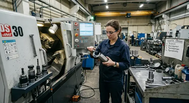
When the first part is in tolerance but the series isn’t, clamping often gives the simplest and most unpleasant reason. The first blank can seat well, but then the chuck, jaws or stop begin to repeat a different datum. The size doesn’t drift immediately, and that confuses people.
Start by looking not at the number in the report but at how the part sits in the chuck. If the clamping force feels different on the first and the tenth part, there will be no repeatability. On the machine you can see this by marks on the surface, by changing runout and by the operator having to “adjust” the seat by hand.
Cleanliness matters more than it seems. A bit of fine chip on a jaw, stop or datum surface is enough for the part to sit with a tilt of a few hundredths. It may not show on the first part but accumulates in the series.
A quick check comes down to four questions: is there dirt, an oil-and-chip mixture or nicks on the jaws and stop; does the first and subsequent blanks clamp the same way; does the operator change the insertion depth or rotation angle of the blank; what runout does the part show after reclamping.
Pay special attention to thin-walled and long blanks. Strong clamping easily distorts such parts, and the size in the chuck looks normal only until unloading. After release the metal “relaxes” and the series begins to wander. If the part is long, bending adds up, especially with a large overhang.
There is a simple test. Machine a part, measure it, then reclamp it in the same chuck and check runout again. If readings change noticeably after reclamping, the problem is often not the tool or the program but the seating.
Another common source of scatter is the habit of placing each blank slightly differently. One operator firmly pushes into the stop, another leaves a barely noticeable gap. On a CNC lathe such a small detail easily turns into a stable drift through the series.
If in doubt, start with the simple: clean the seating surfaces, check jaw contact, mark insertion depth and compare runout after reclamping. It takes minutes and can save a whole shift of troubleshooting.
How the tool changes size during the run
When the “first part in tolerance, series not” pattern repeats, the tool often leaves the clearest trace. Size rarely drifts randomly. Usually it changes in a pattern: after several parts, after an insert change, or only on the finish pass.
First compare sizes before and after an insert change. If a new insert immediately changes the result, look not only at offsets. Check how the insert sits in the pocket, whether there is chip under the support, whether the screw pulls it sideways. Even fine chips in the seat produce a noticeable shift.
It’s useful to record after which part the drift starts. Not “around the end of the batch” but exactly: after the 8th, 15th or 30th part. Such records quickly separate wear from random scatter. If the size drifts at almost the same part number, it looks like normal cutting-edge wear.
Don’t look only for obvious wear. Buildup on the edge is often guilty. From the outside the insert may still look normal, but metal can accumulate on the top and change the cutting geometry. Then the size can swing both ways, and surface finish usually degrades before someone notices the dimensional change.
Also check tool overhang and holder rigidity. Excessive overhang makes behavior unstable: the first part comes out fine, then the tool deflects more under load. The same happens if the toolholder doesn’t sit well in the toolpost or the seating area already has dents.
A simple comparison of roughing and finishing passes works well. If size drifts mainly on the finish pass, suspect the edge, buildup or tool deflection. If spread is visible already on roughing, look wider: rigidity, cutting mode and holder clamping. If after changing an insert everything returns to normal for only a few parts, wear or buildup is almost certainly the cause.
A small example. A shaft is turned in a series and after 12–14 parts the OD starts increasing by 0.02 mm. They change the insert and the cycle repeats with nearly the same number of parts. This no longer looks like a program error. It makes sense to check insert life on that material, the cutting mode and real tool rigidity instead of twisting offsets after every fifth part.
How temperature shifts the size
If the first part is in tolerance and the series isn’t, heat is often involved. The machine, spindle, chuck, tool, part and coolant warm up at different rates. While components reach operating regime, size can slowly drift even without program changes or corrections.
After a cold start this is especially visible. The first part still falls within tolerance, then the size shifts by a few hundredths. After a pause the pattern may repeat because the machine and fixtures cool down again.
What creates a false picture
Often operators compare measurements that shouldn’t be treated the same. One part is measured immediately after machining, another after 10 minutes when the metal has cooled. In the table it looks like random scatter, though the cause is the same: different temperature at the moment of measurement.
Therefore keep one checking order. Warm the machine the same way before each batch, measure parts after the same interval from machining, don’t mix hot and cold measurements in one record, and note coolant temperature and stability of its supply.
Even a simple timestamp helps. If the size drifts right after start, heating is to blame. If the shift grows toward the middle of the shift, check spindle heating, cutting zones and coolant. If the problem appears after a stop, look for differences in machine state before and after the pause.
How to check without long stops
Run the same operation and record 5–6 parts in a row. Note the machining time, measurement time and machine state: cold start, mid-shift or after a break. Such a log quickly shows where the drift begins.
A simple example. In the morning the turned part measures 30.000 mm; after half an hour the series holds at 30.018 mm; after lunch it returns closer to zero. This is not random or a program error. Here you need to see how the machine warms up and how the coolant behaves.
If coolant flow fluctuates, temperature in the cutting zone also changes. Then the tool cuts slightly differently and size starts to drift. Sometimes cleaning a filter, checking the pump and ensuring the jet hits the point consistently is enough.
When you see not just scattered numbers but the moment of drift, the circle of causes narrows sharply. Instead of a vague “unstable machine” you get a clear picture: start, mid-shift or pause.
Where the setup itself creates variation
Often the size drifts not because of the machine or the tool but because setup actions introduce variation: people change several things during the run and later can’t tell what caused the shift.
On a shop floor with CNC lathes this shows quickly. The first part is good, then one operator adjusts the wear offset, another changes the insert, a third measures the part against a different datum. Formally everyone did useful things, but the series lost repeatability.
A common mistake is simple: one person makes an adjustment, another writes it down later or not at all. An hour later it’s unclear where the two hundredths came from — tool wear, a new insert or an extra correction. Worse is when they “catch” the size after every part. Then the cause doesn’t disappear, it just gets masked for a few pieces.
Discipline helps here. For one check use one measurement method, one measurement point and a clear rule when corrections are allowed. If you change clamping, insert and program at once, the result turns into noise.
A simple working order: first run the series for several parts without extra tweaks; then check for a directional drift; only after that change one factor and repeat a short test. This approach is less exciting than constant fine-tuning, but it gives an answer.
Where the program shifts the size
Sometimes the logic of the program, not the clamping or tool, shifts the size. The “first part in tolerance, series not” case often appears after setup when the trial run follows one scenario and the series runs another.
First compare the active tool offset with the setup map. The screen may show the right tool number but the machine might take the wrong wear cell or old geometry. This happens after a rushed re-setup: the insert was replaced but the offset stayed from the previous batch. On the part it looks simple: the first piece is fine, then size slowly drifts.
Then check for leftover temporary offsets. In the previous batch the operator could have slightly adjusted the size via wear, local zero or manual edit in the program. If that change wasn’t removed, the new series starts on someone else’s base.
Usually check four things: does the tool number match the correct offset line, is there a temporary shift left in memory, is the operator running the correct program version, and does the first cycle match a restart after a pause.
The last item is often underestimated. On first launch the setup operator might go frame-by-frame, start cutting not from the beginning, skip roughing or change the entry point. After a pause the operator presses the usual start and the machine runs the full cycle. If the program leaves a different allowance before the finish pass, the size will already be different.
Also look at the finish pass and the tool retract. If the program approaches the tool differently, changes feed before the finish or withdraws the tool too early, the size wanders even with correct clamping. On turning this is especially noticeable on diameters with tight tolerances.
One more simple check: open the program name and number before the series. On the floor it’s easy to confuse the current version with an older copy, especially if names are similar. Five minutes of verification often saves a whole batch of scrap.
How to build a cause map step by step
When the “first part in tolerance, series not” case repeats, don’t try to change clamping, offsets and tool at once. If you change everything in one day you get noise instead of an answer. You need a short test where almost all conditions are the same.
First fix the datum. Use one batch of material, one insert and keep one operator for the whole test. That removes unnecessary variables. If another person tightens the jaws or tweaks an offset in the middle of the series the picture collapses.
Then proceed step by step:
- Run 10–15 parts without extra adjustments. Touch offsets only if the size goes out of limits.
- Measure the same dimension on every part at the same location. Immediately record part number, actual size and time.
- Mark separately what happened before a measurement: machine pause, reclamp, insert change, spindle warm-up, offset correction.
- Change only one factor at a time. First check clamping, then tool, then temperature, then program.
- After each step look at the size line across parts, not just one part. Search for where it changes slope or jumps.
Usually the picture speaks for itself. If size creeps slowly in one direction, heating or tool wear is often guilty. If a jump appears after reclamping, inspect jaws, datums and clamping force. If size breaks after an insert change, compare overhang, seating and offsets.
Draw a simple table rather than relying on memory. Ten rows already do more than an hour of arguing at the machine. If after one change the graph straightens, don’t close the case yet. Repeat a short series under the same conditions. A cause is found only when the result repeats.
Common mistakes when searching for the cause
The most common mistake is simple: blame the machine immediately. It’s convenient, but almost always premature. If size drifts in a series first check the chuck, jaws, cleanliness of seating and clamping repeatability. One burr on the datum or varying overhang often creates more scatter than the machine itself.
Another trap is to look only at the first and the last part. Two points don’t tell you what happens between. Size may slowly drift from heating or jump every other part due to clamping or tool play. You need intermediate measurements, better at the same step: 1st, 5th, 10th, 20th part.
If the operator corrects offset after every piece, they erase the trace of the cause. The series then lives by manual control, and it becomes unclear whether tool wear, temperature or extra setup actions produced the drift. First collect facts, then change offsets. Otherwise the search is blind.
Measurements with different instruments also confuse. One micrometer shows one value, another shows a different one, and a caliper adds its own scatter. If one person measures on the machine, another at the QC bench and a third with another tool, you compare not parts but measurement methods. For a single test use one instrument, one method and one measurement point.
Record four things: part number in the series, actual size, who and when changed an offset, and which tool and clamping were in place at that moment. Without such notes the shop argument quickly turns into guessing. One person remembers changing an insert, another insists it was the chuck, a third didn’t see any correction.
When the complaint “first part in tolerance, series not” appears, the fault rarely lives in a single place. People often look too narrowly. If you start with clamping, measure by one scheme and don’t tweak offsets after every part, you find the answer faster.
A short shop example
On a CNC lathe they turned a shaft with an OD of 40 mm. The first part was in size, QC showed OK, and the series continued. By the twelfth part the diameter slowly grew.
The setup operator did the usual: adjusted the tool offset a bit. The next 2–3 parts improved, but then the size drifted again. This pattern is familiar: it seems like the tool alone is guilty, though usually the cause isn’t a single factor.
When they analyzed the case step by step they found two sources. The chuck and jaws warmed noticeably after the first parts and clamped differently than on the cold start. At the same time the insert started to gather buildup on the cutting edge. Because of this cutting became less consistent and diameter less stable.
The check took little time: they stopped the series and let the clamping node reach working temperature, cleaned jaws and seating from fine chips, inspected the insert under magnification, replaced it and moved the inspection point so measurements were taken after the same pause and at the same location along the shaft.
After that the picture changed. They no longer considered the first parts on a cold machine as representative and waited for a stable regime. The series ran steadier and size stopped noticeably wandering from part to part.
This example shows a simple point: one correction rarely fixes size drift in a series. If the chuck changes clamping force due to heating and the tool cuts differently because of buildup, an offset only masks the problem for a few pieces.
It’s better to look at the whole chain: how the chuck clamps, how the insert behaves after the first passes, when the operator measures size and whether measurement conditions are equal. When the shop compiles such a cause map, setups run calmer and series hold size without constant tweaking.
Quick checks before a new series
Before starting a series spend 10 minutes on consistent preparation — it’s cheaper than chasing drift after every fifth part. When the first part is in tolerance but the series isn’t, the cause often lies not in one big failure but in two or three small things at once.
A short, consistent checklist eliminates the most common sources of scatter before the first run. Clean datum surfaces, jaws, stops and seating. Even fine chips or a coolant film change the seating and spoil clamping on a lathe. Warm the machine by the same short routine: run axes idle, spin the spindle at working speed and do a couple of trial cuts without finish size. Check the program version, active offsets, zeros and wear. Take 3–5 consecutive measurements the same way: one instrument, one point, one force, one person. Also inspect the tool before starting. If the edge is already worn in, CNC tool wear will show up right after the first good part.
Warming up is often skipped in the morning or after a long break. At this moment temperature and repeatability are directly linked: the bed, spindle and clamping unit haven’t reached the usual regime and people try to hold size as if it were mid-shift.
A simple log sheet works well: date, machine, program, offset, material, 3–5 consecutive sizes. After a few runs the pattern becomes clear. If the first measurement is normal and the fourth drifts one way, check heating, clamping or wear. If the scatter jumps without direction, chips, datum or measurement method are usually to blame.
If size drift repeats on similar parts, don’t always treat the symptom with manual offsets. In those cases it’s useful to check clamping scheme, tooling selection and service approach with EAST CNC. The company supplies CNC lathes for metalworking and handles commissioning and service, so these practical analyses are a normal part of their work. The EAST CNC blog on east-cnc.kz also regularly publishes equipment reviews and machining tips that help see the problem more broadly than a single failed part.
FAQ
Why is the first part in tolerance, but the series drifts?
Usually the first part comes out after a cold start, and then the machine, chuck, tool and the workpiece heat up and start behaving slightly differently. Individually these shifts are small, but together they pull the size off. Often there is more than one cause. Clamping changes after warming, the cutting edge gradually wears in, and manual adjustments only accelerate the drift.
Where should I begin searching for the cause?
Start not with guesses but with the moment the drift begins. See on which part the size stops holding: the 3rd, the 10th, or after a insert change. This immediately narrows the causes. An early drift more often relates to clamping and datum; a later one — to heating, wear and accumulated corrections.
How to quickly tell if the clamping is the problem?
Remove the part, measure it, then reclamp it in the same chuck and check runout again. If the readings change noticeably after reclamping, inspect the jaws, stop, cleanliness of the seating and the insertion depth. It's also useful to compare the first and the next few blanks. If clamping force or marks on the part change, repeatability will be poor.
How to distinguish tool wear from random scatter?
Track the size by part order and note exactly when it starts to drift. If the pattern repeats almost at the same part number, the cutting edge is likely losing its life or buildup is forming on it. Also check the insert seating. Even fine chips under the support or a tilt in the pocket immediately change the result.
How to check whether temperature is causing the size drift?
Compare parts measured under the same conditions. If you measure one immediately after machining and another a few minutes later you mix hot and cooled sizes. Record the start time, measurement time and machine state: cold start, mid-shift or after a break. Such a log quickly shows when heating starts to affect size.
Should I adjust compensation after every part?
No. If the operator adjusts size after every single part, they are more likely to hide the cause than find it. When corrections are made after each piece the series lives under manual control. Better let several parts run without adjustments and observe the trend. Only then make one deliberate correction and check the result.
How to measure correctly so I don't get confused?
Use one instrument, one measurement point and one person for the whole test. Otherwise you get variation not only from the part but from the measurement method itself. Also keep the same pause after machining. Hot and cold parts must not be listed together without a note.
Can the program itself shift the size?
Yes. It happens after re-setup or a rushed start. The machine may take the wrong wear offset cell, old geometry or another program version. Check that the first cycle and a normal restart run the same way. If the setup operator tested one scenario but the series runs another, size will change easily.
What to do before a new series or after a break?
In the morning and after a long pause don't consider the first successful part proof of stability. First let the machine and clamping unit reach the normal state. A short, consistent warm-up, clean jaws and a quick check of several consecutive parts help you see true repeatability rather than a lucky first shot.
When should I call in specialists?
If the drift repeats on similar parts and you have already checked clamping, tool, temperature and program, involve specialists. Especially if the issue spans shifts or returns after each setup. In that case review clamping scheme, machine selection and service approach with EAST CNC. They supply CNC lathes and provide commissioning and service, so practical troubleshooting like this is within their experience.