Deep Hole Drilling: The Order of Diameter Transitions
Deep hole drilling requires a precise order of diameter transitions. Here’s how to reduce drift and remove the shoulder at the joint.
Where the step at the joint comes from
A step at the diameter joint rarely appears on its own. Usually, it shows up in the short moment when the tool loses direction and the edge of the transition starts pulling it to the side. That is enough for the axis to shift slightly and leave a visible mark at the joint.
The first reason is simple: the tool catches the edge of the transition. If one section has already been machined and a rough allowance still remains nearby, a sharp edge appears at the joint. When a long drill or boring tool reaches that point, the edge pulls it sideways. The shift may be small, but in a deep hole even tenths of a millimeter become noticeable quickly.
Then comes the loss of support. In a narrow diameter, the walls partly guide the long drill. As soon as the cutting part enters a wider section, that support is almost gone. The tool no longer moves as confidently and may start to drift a little. If feed is too high at that moment, a shoulder remains at the joint instead of a smooth transition.
Chips also often ruin the result. In a deep hole, there is already little room for them, and a narrow section makes it even harder for them to escape. Chips build up, rub against the walls, and start pushing the drill sideways. After that, the tool enters the next diameter along a different axis than the one it started with.
There is also a less obvious reason: a rough roughing pass. If it leaves a wave, scratch, or slight taper, the joint will later repeat that defect. The finishing tool does not always correct the shape completely. Often it only highlights the mistake that appeared earlier.
In practice, it looks like this: first the hole runs straight, then a ring appears at the diameter transition, and after that the axis shifts slightly. For a part, this is an unpleasant small defect. Under a bearing, bushing, or fit, such a joint may already need rework.
Usually, the problem comes from three things: the edge at the joint, loss of support, and poor chip evacuation. If at least two of them coincide, the step appears very quickly.
What to check before starting
If the axis drifts right at the beginning, the correct order of transitions will not save the process later. Before the first part, it is worth removing a few simple risks. It takes little time, but it often eliminates the cause before cutting even starts.
First, check the drawing and the process sheet. Look not only at the total hole depth, but also at the length of each section and the point where the diameter changes. An error of 0.5-1 mm at the transition is already enough to create a noticeable shoulder. The problem often starts with different reference bases too. If the drawing gives depth from the face but the machine zero is set from a different surface, the joint will shift even with the right tool.
Then check the runout of the whole chain: the drill, the chuck, and the arbor. One measurement at the shank is not enough. What matters much more is the runout at the cutting end, because that is what drives the drill off course in the material. In a deep hole, even a small deviation adds up quickly.
It’s better not to argue with tool overhang. Leave only the overhang needed for the depth and safe approach. An extra 20-30 mm noticeably reduces stiffness. Also check the part clamping. If the body or blank shifts even a little under load, the drill will follow a softer path.
Before starting, it is enough to quickly check four things: which reference base each depth is set from, where the diameter transition starts and ends, whether the tool overhang can be reduced, and whether the clamp holds axial load without movement.
Also look at the coolant. It should not just reach the cutting zone, but steadily carry chips out. If chips build up in the depth, the drill starts rubbing, heating up, and pulling the axis aside. Before a batch, it is better to check coolant delivery, channel cleanliness, and actual chip evacuation on a test pass. If chips come out unevenly or turn dark, it’s better to stop right away, not after the tenth part.
How to choose the order of transitions
If the part has several diameters, do not start with the largest one. For a deep hole, that is almost always a bad choice: support is weak, the axis drifts, and a step remains at the joint. It is safer to set the main axis first in the narrowest and deepest section of the hole.
The logic is simple. The smallest diameter goes to full depth and sets the direction for all following operations. After that, each larger diameter is opened only to its own length, no deeper. That way the tool pulls less to the side and the transition between sections comes out cleaner.
If the part has diameters of 12, 18, and 24 mm, it is safer to go like this:
- Machine 12 mm to full depth.
- Open 18 mm only to its calculated length.
- Machine 24 mm only on the short entry section.
- Leave a small allowance at the joint and remove it before the finishing pass.
Jumping over a size often causes problems. If you go from 12 mm straight to 24 mm, the load on the cutting edge increases, the tool catches the material more strongly, and the transition shoulder comes out rougher. Moving through neighboring sizes works more smoothly: each next tool removes a moderate layer and disturbs the already established axis less.
It is better not to take the diameter joint down to zero during roughing. It is easier to leave a small allowance and remove it at the end, when all diameters are already in place. Then the finishing tool cuts the remainder in one smooth pass instead of trying to correct an old offset.
On CNC lathes, this approach is especially convenient: you can set the length of each section in advance and keep the tool out of places where its diameter is no longer needed. On paper, the route sometimes looks longer, but in practice it often saves time on rework and checks.
Pass order step by step
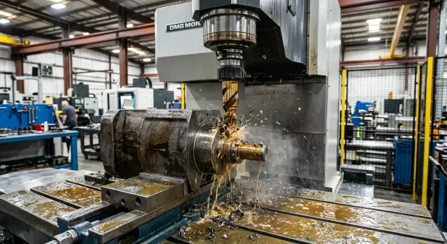
When machining deep holes, the order of operations affects the geometry almost as much as the drill itself. If you open a large diameter right away, the tool is more likely to leave the axis, and a visible mark remains at the joint later.
It is usually better to go from a short guiding entry to full depth, and then open the next steps by length. This order holds the axis better and reduces the risk of shifting at the transition.
- First make a short centering entry. A few millimeters are usually enough to set the axis and stop wandering at the start. In a ductile material, do not make this entry too deep: it can also introduce an error.
- Then drill the pilot or first working diameter to full depth. This is what sets the path for all later machining.
- Next, open the next diameter only to the length required by the drawing. Do not try to remove all the allowance in one long pass right away.
- Repeat the same order for the remaining steps. At the end, carefully clean up the transitions to remove the mark from tool entry and avoid leaving a shoulder.
In practice, the scheme is simple: first set the axis with a short entry, then carry out the deepest pass with the smaller diameter, then open the middle step, and only after that the upper one. Not the other way around.
There is also a useful trick for the transition itself. When the tool approaches an already drilled area of another diameter, it helps to reduce the feed slightly over the last few millimeters of entry. Then the edge crosses the boundary more gently, and the transition comes out cleaner.
If the first part shows drift or a slight ring at the joint, do not rush to change the whole route. First check whether you are opening the larger step too early and whether chip evacuation between passes is sufficient.
How to keep the hole axis steady
The axis does not drift in the middle of the stroke, but at the moment the tool receives its first side load. This usually happens because of excess overhang, tight chips, and a sharp entry into a new step. If you remove these causes, the hole runs noticeably straighter.
Start with the simplest thing: leave only the overhang the tool really needs. Every extra millimeter makes the drill more flexible. In a deep hole, you feel that immediately: the tool begins to spring, and then the axis shifts. If the part and setup allow it, it is better to reposition the clamp or change the holder than to work with a long overhang just in case.
At the entry into a new step, do not suddenly speed up the feed. At that moment the cutting edges have not yet stabilized, while the load is already changing. Because of this, the drill pulls to one side, and the shift becomes visible at the joint later. A calm entry usually helps: pass the first few millimeters more gently, then return to the working feed.
If chips are hard to evacuate, do not force the pass to the end at any cost. It is better to make an intermediate withdrawal, clear the chips, and enter again along the same axis. This is especially useful on ductile steels, where chips quickly pack into the flutes. One extra withdrawal costs seconds, but it often saves both the part and the tool.
Keep an eye on the coolant too. It should reach the cutting zone directly, not just flow nearby. When the jet misses the cut, the edge overheats, chips break less cleanly, and the drill starts looking for an easier path. On deep holes, you can often hear it in the sound: cutting becomes harder, and the chips turn darker.
Early signs of drift are usually visible right away. The cutting sound becomes uneven, chips come out in different shapes from the left and right flutes, spindle load rises without a change in the mode, and a shiny mark appears on one side at the entry or transition. If you notice even one of these signs on the first part, it is better to correct the settings immediately.
Example for a housing with three diameters
If a housing needs one axial hole with three zones, the pass order directly affects both drill drift and transition quality. Take a simple case: 8 mm to a depth of 120 mm, then 12 mm to 70 mm, and 18 mm to 25 mm from the entry side. On such a part, the error usually appears not at the end, but right at the beginning, when the main axis is formed with the wrong tool.
For this setup, you first need to get an 8 mm hole to the full depth of 120 mm. This diameter sets the axis for all further machining. A long, thin tool is the most prone to drift, so it needs a clean entry zone that has not been opened yet.
The working sequence is:
- Form 8 mm to the full depth of 120 mm.
- Open 12 mm only on its own section, to 70 mm.
- Machine 18 mm only on the first 25 mm.
- Clean up the transition between 8 and 12 mm with a separate short pass.
The last step is often skipped, and that is a mistake. After the main 12 mm pass, a thin ring of metal may remain at the joint. That is what looks like a step, even though in essence it is the mark left by tool exit or a small remainder after opening. A short rigid pass to the transition depth removes this ring much better than repeating a long drill pass over the full length.
This order works better for one reason: each next tool follows an already established axis instead of trying to create it again. The 12 mm diameter opens only the middle section and almost does not affect the far part of the 8 mm hole. The 18 mm diameter works only on the first 25 mm, so its risk of drift is small if the entry is already coaxial.
If you do it the other way around and start, for example, with 12 mm or 18 mm, the entry section becomes wider too early. Then the 8 mm drill loses part of its guide at the entry, starts searching for position, and may shift the axis. From the outside it looks minor, but at the 8 and 12 mm joint a noticeable step later appears, and sometimes even a trace of runout on the wall.
For the first part, it is useful to check not only the depth dimensions, but also the 8-12 mm transition itself. If the shoulder is even, with no ring and no offset, the order is correct.
Where people make mistakes most often
The most common mistake is to start immediately with the large diameter in order to save one pass. On a short hole, that sometimes works, but in a deep channel this quickly pushes the drill sideways. After that, all following tools already run on a shifted axis, and a step appears at the joint.
The second mistake is to skip an intermediate size when the transition is too large. If the diameter difference is significant, the load on the edges becomes uneven. The tool starts rubbing harder on one side, heats up, and holds direction worse. As a result, the smaller diameter drifts, and when you move to the next size, a ring remains that is hard to remove without separate rework.
Another common miss is leaving the joint after roughing as it is. A roughing tool often leaves a slight taper, scratch, or burr at the transition. If the finishing pass does not cover this area, the step remains even when the diameter at the entry is correct.
People also make mistakes in inspection. The operator checks the diameter at the entry, sometimes verifies the second size, but does not measure the depth of the step or look for an axis shift inside. For assembly, that is a bad scenario: the part may pass a quick check and then seize when installed in the unit.
The problem is usually shown by these signs: chips come out unevenly already on the first deep pass, the tool heats up noticeably at the diameter transition, the gauge passes the entry but catches deeper inside, and the step does not disappear completely after boring or reaming. If one of these signs appears on the first part, it is better to bring back the intermediate diameter, add a finishing pass at the joint, and check the transition depth again.
Quick check after the first part
After the first part, do not rush to start the whole batch. In 10-15 minutes, you can tell whether the axis is drifting, whether the size is holding, and whether the step at the joint is growing.
First, measure the diameter not in one place, but in at least three: at the entry, in the middle, and near the bottom. This often shows the problem before scrap becomes visible from the outside. If the size is within tolerance at the entry, already larger in the middle, and even larger at the bottom, the tool is pulling sideways or the mode is too aggressive.
It helps to write down the results for each diameter right away. Then you can see not just the fact of a defect, but its shape. For example, 18.00 mm at the entry, 18.03 mm in the middle, and 18.08 mm at the bottom almost always point to drift rather than a random measurement error.
Check the depth of each step separately. Not the total hole depth, but the length of each section in its own diameter. An error of 0.2-0.3 mm at an early transition is often what creates that very step, even if the diameters themselves came out almost right.
It is better not to judge the joint by eye. If access allows, use an endoscope or a gauge. If the hole is deep and the transition is hard to see, an impression or comparison with a good first sample helps. Even a small ring should be treated as a problem right away. By itself, it usually does not disappear; it repeats from part to part.
Another quick clue is the chips and the cutting sound. If the chips have become darker, shorter, or break differently than before, the mode has already changed. If the sound becomes sharper, a whistle appears, or short impacts are heard, the tool may be entering the transition off-axis.
A good habit is simple: after the first good part, record the dimensions, depths, appearance of the joint, and notes on the sound. Then before the second part, it is already clear what to adjust - feed, transition order, tool overhang, or the point where the diameter changes.
What to do next
If the first part came out well, it is best to lock that result into the operation sheet right away. When the sequence is kept only in memory, after a few shifts each operator starts changing the feed, entry depth, or moment of transition to the next diameter a little differently. That is how drift and a step at the joint come back.
The sheet should record not only the sequence of passes, but also the details that are usually forgotten: which drill to start with, where to do the check, when to retract the tool, and at what signs to stop the process. It is enough to record the order of diameters and depths, the speed and feed for each transition, the coolant delivery method, and the allowed deviation in axis and joint.
After any tool or holder replacement, it is better to repeat the test. Even if the part number is the same, the new tool may behave differently because of runout, wear in the seating, or slightly different cutting edge geometry. On paper, the set is the same, but in operation the difference can already create noticeable drift on the first part.
If you are launching a new part, do not start with the mode “just like the last batch.” First check whether the machine can handle that overhang, whether the clamping is stiff enough, and whether coolant flow is stable. Weak coolant supply can quickly ruin the whole process: chips do not leave in time, the drill drifts, and a mark remains at the transition that is hard to remove later.
A useful habit is to make one more test part with the same settings after the first acceptable one. If both parts match in axis and joint quality, the process can already be considered stable. If the second one shifts, it is better to look for the cause right away: in the tool, clamping, coolant, or the stiffness of the setup.
When the problem is no longer about settings but about the machine’s capabilities, it is worth reconsidering the machine and the tooling itself. EAST CNC works in Kazakhstan as the official representative of Taizhou Eastern CNC Technology Co., Ltd. and helps with machine selection, commissioning, and service maintenance for metalworking tasks. This is especially relevant where the part has a long channel, several diameters, and almost no room to correct scrap.
FAQ
Why does a step appear at the diameter transition?
Most often, the step appears because three things happen at once: the tool catches the edge of the transition, loses support as it enters the larger diameter, and runs into chips. Even a small sideways push is enough for the axis to shift and leave a shoulder at the joint.
Which diameter should you start with?
Usually, you start with the smallest and deepest diameter. It sets the axis for all following passes, and then each larger size is opened only to its own depth.
Do you need a short centering entry before deep drilling?
Yes, a short centering entry often helps. A few millimeters are usually enough to set the direction and stop the tool from wandering at the start.
Can you go straight to the larger diameter to save time?
It’s better not to do that in a deep hole. A large diameter removes the guiding section too early, the tool holds the axis worse, and the smaller pass is more likely to drift sideways.
What order should you choose for a hole with three diameters?
First pass 8 mm to the full depth of 120 mm, then open 12 mm only to its own length, and machine 18 mm only near the entry. At the end, use a separate short pass to remove any leftover material at the transition if a shoulder remains there.
What should you check before the first part?
Before starting, check the depth reference base, the point where the diameter changes, runout at the cutting end, the tool overhang, and how firmly the part is clamped. Then see how the coolant reaches the cut and how the chips come out on a test pass.
How can you tell that the tool is already drifting off axis?
The axis usually gives itself away right away: the cutting sound becomes uneven, the chips come out differently from the left and right flutes, the load rises without a change in settings, and a shiny mark appears on one side at the transition. If you see that on the first part, it’s better to correct the settings immediately.
What should you do if you already see a ring at the transition on the first part?
First, don’t change the whole route. Most often it helps to reduce feed before entering the new step, shorten the overhang, improve chip removal, and add a short finishing pass at the joint.
Should you leave an allowance at the diameter transition?
Yes, a small allowance at the transition is usually a good idea. The roughing pass should not bring the step down to zero, because the finishing tool can then remove the remaining material more calmly in one smooth pass.
How do you quickly check the first part after machining?
Measure each diameter not only at the entry, but also in the middle and closer to the bottom. Then check the length of each step and the joint itself separately: if there is already a shoulder or offset there, the problem will usually become even more noticeable in the production run.