Cutting Ductile Steels Without Long Continuous Chip
Cutting ductile steels often produces long continuous chip. Learn how chipbreakers, depth of cut, and nose radius help on different material batches.
Where long continuous chip comes from
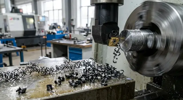
Long continuous chip appears when the metal does not break into short pieces, but stretches into an unbroken ribbon. This is typical for tough and ductile steels: the material flows easily along the rake face of the insert, the chip curls, but does not tear. This can happen even on a stable machine with a new insert.
The problem is more than just inconvenient. Long chip catches on the chuck, toolholder, and workpiece, hits the part, and ruins the finishing surface. The operator has to stop the machine more often and remove the buildup by hand. That takes time and raises the risk, especially in production runs.
The first signs are easy to spot during test cuts: the chip comes off as a long shiny ribbon or a tight spiral, wraps around the part or tool, the cutting zone makes impact sounds and uneven scraping noises, and random marks appear on the surface. Sometimes the chip shape changes noticeably from one pass to the next without a clear reason.
Usually, it is not one parameter. Chip shape is influenced at the same time by the steel itself, the material batch, the workpiece surface condition, speed, feed, depth of cut, insert geometry, and coolant flow. If even one factor moves out of the working range, the chip stops breaking and starts stringing.
That is why feed alone rarely solves the problem. Yes, increasing it sometimes helps: the chip gets thicker and presses harder into the chipbreaker groove. But this approach has limits. Too much feed hurts surface finish, increases tool load, and does not always solve the issue if the depth of cut is too small or the insert geometry is wrong.
In the shop, long chip usually means one simple thing: the current cutting conditions and geometry do not match the specific batch of metal. It is better to catch that early, before it turns into scrap, downtime, and manual clearing of the cutting zone.
Why one batch cuts differently
The same steel grade on the label does not guarantee the same cutting behavior. One batch gives short chip, the next pulls a long ribbon, even though the machine, insert, and settings are the same. For ductile steels, that is a normal situation.
The reason is often found in small differences you cannot see from the material name. Slightly higher hardness, a different melt, another rolling or drawing process, a denser scale layer on the surface, and the chip bends differently. Even the first pass can behave harder than later machining of the same bar.
A bar from a different melt can change the picture more than it seems. The chemical composition still stays within spec, but ductility, strength, and behavior under heat in the cutting zone shift a little. That is enough for old settings to stop breaking the chip.
Surface condition matters too. If a new bar has a dense outer layer from rolling, the tool enters it differently than it does into already cleaned metal. That is why the first passes may be noisy, produce burrs, and throw long coils, while the process later becomes somewhat more stable.
Do not assume the old setup is correct by default. It only worked for the previous batch. Sometimes a small shift is enough: increase feed, change depth of cut, or switch to an insert with a different chipbreaker and nose radius.
After a material change, it helps to watch several signs at once: chip shape, cutting sound, the surface after the first passes, and spindle load. If yesterday a batch ran calmly at 1.5 mm depth, but today the chip wraps around the chuck with the same settings, that is not necessarily the operator's mistake. More often, the new batch simply needs a different setup.
In production runs, this becomes especially clear. If you spend 10 minutes at the start of a shift on test cuts and check the chip, you can avoid hours of downtime and extra insert wear.
How the chipbreaker changes chip behavior
The chipbreaker controls the chip path right after cutting. The groove on the rake face of the insert makes the chip curl faster. If the bend is sharp enough, the chip loses stability and breaks into short pieces instead of stretching into a long ribbon around the part.
A shallow, wide chipbreaker usually works better with thicker chip. At a normal feed and noticeable depth of cut, it gives the chip room, then squeezes and breaks it without extra pressure on the edge. If you use the same chipbreaker too lightly, the chip becomes thin, springs back, and often comes off long.
A deep chipbreaker behaves differently. It grabs thin chip earlier and is better for light cuts with lower feed. But on heavy cuts, that geometry starts to get in the way: the chip hits too early, the load rises, and the edge heats up more.
A common reason for long continuous chip is simple: the chip passes outside the active part of the groove. That happens when feed is too low for the selected insert, the depth of cut is below its working range, or the geometry itself is designed for a different setup. In the end, the chip slides over the insert surface, bends slightly, and leaves as a ribbon.
For a light cut, a deeper chipbreaker and a feed without unnecessary caution are often the better choice. For medium and roughing cuts, you usually need a more open groove that has enough room for thick chip. If chip comes off as a ribbon at shallow depth, first check the insert geometry and feed, not the speed. When a small feed increase breaks the chip right away, the problem is usually a mismatch between the chipbreaker and the setup.
On a new steel batch, this shows up fast. One batch starts breaking chip at 0.18 mm/rev, while another needs 0.22 mm/rev on the same tool. That is why it helps to look not only at the material grade, but also at the insert's working window. If it is too narrow for your cutting conditions, it is easier to change the chipbreaker geometry than to keep adjusting speed alone.
What depth of cut does
Too small a depth of cut often creates that same long ribbon. The tool removes only a thin layer, the chip comes off narrow and soft, and the chipbreaker works weakly. Ductile steel does not break, but stretches and wraps around the chuck, part, or toolholder.
This is very clear on ductile steels. If the depth of cut is below the insert's working zone, the chip barely gets the bend it needs. It slides along the rake face, but does not press into the chipbreaker geometry the way it should.
As depth increases, the chip becomes thicker and stiffer. It is harder for it to simply pull out as a ribbon, so it bends more strongly and breaks earlier. Even a small step up often changes the picture: long spiral chip turns into short arcs or half-rings.
But depth cannot be increased without limit. Every setup has its ceiling: machine power, clamping rigidity, tool overhang, chuck condition, and the insert itself. If you go past that line, the spindle starts working harder, chatter appears, the edge overheats, and the surface gets rougher.
The rule of thumb is simple: stable cutting sounds and looks stable. The sound is even, chip comes off predictably, load does not jump, and the size stays within tolerance. If the machine starts vibrating or leaves a torn surface after you increase depth, the calm setup is already gone.
It is best to check the effect of depth on a short test and without changing the other parameters at the same time. Keep the same feed, speed, and insert, then make several short passes with a gradual increase in depth. Compare chip shape and cutting sound, and stop right away if vibration or load rises.
In practice, this test takes just a few minutes. If a 0.4 mm cut gives long continuous chip, but at 0.8 mm it starts breaking, you have found the working window. After that, all that remains is to see whether it holds across the whole run.
Why the nose radius matters
The insert nose radius affects more than just the tool mark on the surface. It changes how the chip bends, compresses, and breaks. When machining ductile steels, it often decides whether you get short chip or a long ribbon.
A smaller radius usually helps chip break more easily. It concentrates deformation more strongly in the cutting zone, so the chip curls faster and reaches the chipbreaker earlier. This is especially noticeable at shallow depth of cut and on finishing passes, where the chip is thin by nature.
A larger radius behaves differently. It cuts more smoothly and, on a stable machine, often leaves a more even finish, but the chip comes off more gently and takes longer to break. If feed is low and the steel is ductile, that kind of radius often pulls long chip instead of breaking it near the insert.
A larger radius often wins on surface finish, but not always. On a rigid setup and with finishing allowance, it can give a calmer cut. But if the part is thin, the overhang is large, or the material is sticky, the edge starts rubbing instead of cutting. Then the surface is not better, but worse, and the chip gets longer too.
A smaller radius does not solve everything by itself. It is useful when you need better chip control at shallow depths. But on a roughing pass, it handles shock worse, and the surface mark is usually rougher.
A common mistake is to blame the radius when the real problem is feed. If feed is too low for the chosen chipbreaker, even a good radius will not save the cut. That is why it helps to first compare the actual feed with the insert's working range, then check depth of cut, and only after that change the nose radius. And you need to judge not only the chip, but also the part surface.
A simple example: on a 0.6 mm pass with low feed, an insert with a 0.8 mm radius often pulls a ribbon. The same geometry with a 0.4 mm radius may start breaking chip much earlier. But if you raise feed to a normal level, the problem sometimes goes away even without changing the radius. The radius should always be viewed together with feed, not on its own.
How to set up the process on a new batch
It is better not to put a new batch straight into production. Start with a short test at calm settings. Two to three parts, or a few passes on a blank, are enough. The goal is not maximum output, but to understand how this steel breaks chip.
After the first passes, do not look only at chip size. Pay attention to how it leaves the cutting zone, whether it catches on the chuck, whether it falls under the insert, and whether it leaves marks on the part. If the chip starts to come off as a long spiral, the process already needs adjustment.
It is best to change settings one parameter at a time. If you change speed, feed, chipbreaker, and depth of cut all at once, you will not know what caused the result. In the shop, that almost always leads to extra trial cuts.
In practice, it is easier to go in this order: first choose the chipbreaker, then fine-tune depth of cut, and only then look at the nose radius. That works because the chipbreaker has the strongest effect on chip curling and breaking. If its geometry does not fit, changing the cutting conditions often gives only a temporary result.
Depth of cut also changes the picture quickly. On a very shallow pass, the chip may not enter the chipbreaker working zone at all. Then it comes off long, even if the insert itself is a decent choice. Only after that does it make sense to check the nose radius: a large radius can make cutting smoother, but on ductile steel it can also make chip breaking worse.
After a successful test, it is worth making a short note: which insert and chipbreaker were used, what the depth of cut was, which nose radius worked best, at what feed the chip started breaking reliably, and what the surface finish looked like. A month later, that note can save a lot of time.
Example with two batches of the same steel
On a turning operation for a 52 mm shaft, the first batch of the same steel grade ran smoothly: a CNMG insert with a universal chipbreaker, speed 170 m/min, feed 0.22 mm/rev, depth of cut 1.2 mm. The chip came off as short arcs and fell into the tray. The operator hardly had to watch the cutting zone.
A week later, a second batch arrived with the same designation in the certificate. The settings were left unchanged, but the picture changed right away. The chip became a long ribbon, wrapped around the part, and sometimes caught on the chuck. The surface still stayed within tolerance, but work became much harder: the machine had to be stopped more often to clear the cutting zone.
The first change was only to a sharper chipbreaker geometry. That helped, but did not fully solve the issue. At the entry and exit of the cut, the chip became shorter, but on the long pass it still pulled as a ribbon. The new batch turned out to be more ductile, and at a 1.2 mm depth of cut the chip was still too thin for stable breaking, even with a different chipbreaker.
The process settled after two small adjustments. Depth of cut was increased to 1.8 mm, and the nose radius was changed from 0.8 to 0.4 mm. After that, the chip curled more strongly, broke faster, and stopped catching on the part. Speed and feed were barely changed so that the whole setup would not be altered at once.
This example shows the real picture well. One batch cuts as expected, while another gives long continuous chip at the same numbers. If you only look at the material grade, the reason seems strange. If you look at chip shape and thickness, everything becomes clearer.
One chipbreaker often removes only part of the problem. A stable result usually comes from a combination of three settings: insert geometry, depth of cut, and nose radius. A slight increase in depth helps the chip fully enter the chipbreaker groove, and a smaller nose radius curls it more strongly and often breaks it into shorter pieces.
You should not copy these numbers blindly. But the order of action in such a case is practical: first change the chipbreaker, then add a little depth, and after that check the nose radius. On a new batch, that usually gives an answer faster than a long search through speed and feed settings.
Where mistakes happen most often
The first common mistake is reducing depth of cut to get a cleaner surface. The mark on the part may indeed look neater, but the chipbreaker stops working in its range. The chip comes off as a thin ribbon, does not break, and wraps around quickly.
The second mistake is using one universal insert for every material batch. That is convenient for inventory, but not always for actual work. Even if the steel grade is the same, one batch cuts dry, while another stretches more and sticks to the edge. If the insert geometry is too mild, the chip will not break even at a normal feed.
The third mistake is very common: feed is raised to break chip, but the part surface is not checked. Sometimes the chip really does become shorter, but the surface gets a coarse step, burrs grow on shoulders, and size starts to drift. You need to judge the full result of the pass, not just whether the chip broke.
There is one more bad habit: changing several settings after every part. Higher speed, lower feed, different depth, then back again. After a few parts, it is no longer clear what actually helped. It is much more useful to keep two parameters fixed and move only one across at least several blanks in a row.
Another problem is tolerating chip around the chuck and toolholder for too long. It scratches the surface, blocks visibility, catches on the tool, and sometimes gets dragged back into the cutting zone. In turning, that is a direct path to scrap and extra stops.
If the chip starts stringing again, a short check is usually enough: does the depth match the chipbreaker's range, is the nose radius too large for this pass, did feed spoil the surface, and is chip building up near the chuck. The most expensive mistake here is not the setting itself, but the chaos. When the setup technician makes clear notes by batch and does not turn every knob at once, the cause is found much faster.
Quick check before production
Before starting production, it is not enough to look only at the part size. In the first minutes, it is better to check the chip and the machine's behavior. That often saves more time than cleaning a chuck wrap or pulling a long ribbon out of the work area later.
A good sign is simple: the chip breaks on its own and leaves in short pieces. It does not hang on the part, does not catch on the tool, and does not strike the guard as a long strip. If instead you see a steady ribbon, the process is not ready for production yet, even if the size is still within tolerance.
On test parts, it is also worth checking the surface. It should stay even, without random scratches or tearing. When long chip starts rubbing against the part, the trace changes almost at once: streaks appear, and the shine becomes uneven in places.
Spindle load also gives a useful signal. If it runs calmly without sharp jumps, the setup is close to the working range. If the load rises in bursts, the chip is alternately breaking and stretching back into a ribbon. That often happens on a new batch when the material is a little softer or more ductile than last time.
The check takes 2-3 minutes. Just run the first parts without stopping, listen to the cutting sound, look at the surface right away, compare the current load with the familiar setup, and ask the operator whether he had to interrupt the cycle. If he is already reaching for pause at the start just to clear chip, the run will be difficult.
A normal result looks like this: the cycle runs without frequent stops, the chip comes off predictably, the machine does not jerk, and the surface is clean. After that, the batch can be run with confidence instead of hoping that the long chip will disappear on its own.
What to do next on the shop floor
After a couple of test parts, it is not wise to rely on memory. For ductile steels, a simple table works better: material batch, insert grade and geometry, cutting conditions, chip type, and final surface result. After a month, such a record often saves more time than yet another long setup change.
It is useful to record only the factors that affect chip behavior the most: batch or melt number, insert and chipbreaker, feed, speed, and depth of cut, plus the real result - short chip, long ribbon, wrapping, or marks on the part. Such a table quickly shows a simple truth: the same steel on paper can behave differently on the machine.
For roughing and finishing, it is better to keep different working solutions from the start instead of searching for one universal option. Roughing usually allows a more aggressive chipbreaker, greater depth, and higher feed. Finishing is more sensitive: it more often needs a smaller depth, a different nose radius, and a more careful insert choice to avoid long chip near the finished surface.
Even a good combination of insert and cutting conditions will not work if the system lacks rigidity. Then the chip breaks unreliably, and the sound and surface quickly show that the adjustment margin is too small. That is why, before production starts, it is worth checking tool overhang, clamping rigidity, chuck condition, the machine's overall capacity for the chosen feed and depth, insert wear, and any play in the setup.
If roughing goes well but finishing starts stringing again, it is not always the operator's fault. Often the reason is that the machine, clamping, and tool are already working at the limit for the chosen insert geometry.
When a batch behaves inconsistently, it is better not to guess blindly. In such cases, it helps to review the full setup: material, tool, cutting conditions, machine rigidity, and the actual part requirement. For companies in Kazakhstan and CIS countries, this can be discussed with EAST CNC specialists. The company supplies CNC lathes and machining centers, helps with selection, commissioning, and service, so this kind of discussion often helps you find faster whether the problem is in the cutting conditions or in the system itself. In addition, east-cnc.kz has industry overviews and practical metalworking materials that are useful as working references.
A good result looks simple: you have 2-3 proven setups for roughing and finishing, a clear record by batch, and a clear understanding of when the problem is in the cutting conditions and when it is already in the machine-fixture-tool system.
FAQ
What is long continuous chip?
It is chip that leaves as a continuous ribbon or a long, dense spiral and does not break near the insert. It wraps around the part, chuck, or tool, scratches the surface, and forces the machine to stop more often.
Why does one batch of the same steel cut differently?
Because the same grade on paper does not always behave the same during cutting. A different melt, hardness, ductility, or a dense outer layer on the bar can easily push the process out of its working range.
Where should I start if the chip wraps around the part?
First, do not change everything at once. Check whether the current depth of cut and feed are within the insert's working range, then make a short test with a different chipbreaker geometry.
How can I tell that the problem is the chipbreaker?
Usually you can tell by this: with low feed and shallow depth, the chip comes off as a ribbon, but after a small increase in feed it starts to break. That means the chip was passing outside the working part of the groove, and the insert geometry did not match the cutting conditions.
Why does a small depth of cut often make chip breaking harder?
A small depth of cut gives a thin, soft chip, and it does not press well against the chipbreaker. In ductile steel, that kind of cut often produces a long ribbon instead of short pieces.
When should I change the insert nose radius?
A smaller nose radius often helps on finishing and light cuts, where the chip is thin by nature. It curls the chip more strongly, but on heavier cuts it handles shock worse and usually leaves a rougher surface.
Can I remove long chip just by increasing feed?
Sometimes it helps, but not always. If you only increase feed, you may spoil the surface, raise burrs, and load the tool too much, so feed should be checked together with depth of cut and insert geometry.
How can I quickly test a new batch before production?
Make 2-3 short cuts in a calm setup and watch the chip shape, cutting sound, surface, and spindle load right away. Change only one parameter at a time, otherwise you will not know what actually worked.
What signs show that the process is ready for production?
You can tell right away: the chip breaks on its own, does not hang on the part, the sound is even, the load does not jump, and the surface stays clean. If the operator reaches for pause at the start just to clear buildup, it is better not to start the series.
When is the problem no longer in the cutting conditions, but in the machine or tooling?
That happens when the tool overhang is too large, clamping is weak, the chuck is worn, or the machine is struggling at the chosen depth and feed. In that case, it helps to check the full machine-fixture-tool setup, and for difficult cases, discuss the setup with EAST CNC specialists for selection and service.