Cpk for Machining: How to Calculate Without Confusion
Cpk for machining helps assess dimensional variation but doesn't explain the cause of defects. We cover the calculation, an example and common mistakes.
Why Cpk is often debated
Cpk looks like a convenient answer to a complex question. One number, a reference threshold, and it seems you can quickly tell whether the process is OK or not.
That rarely works like that on the shop floor. One number does not explain why a size drifted toward the upper limit, where the variation came from, or what to fix first. So some people put too much faith in Cpk, while others refuse to look at it at all.
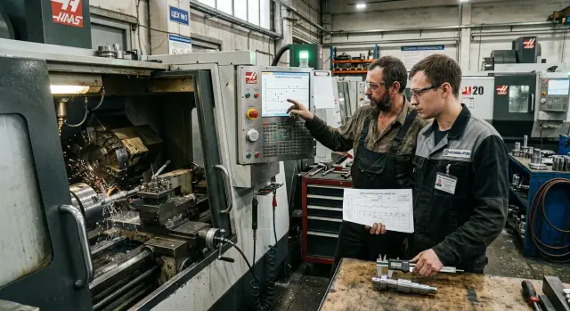
The process engineer always sees a broader picture. They care about cutting parameters, fixture rigidity, part referencing, tool wear, stock allowance and material batch. If a turned dimension "floats," Cpk will show the fact but not name the cause.
Quality control sees a different part of the process. The inspector measures the part, gathers a sample, computes the mean and the variation. That's useful, but QC works with the result. They don't see that the tool edge starts to settle every 40 parts or that the operator tightens the workpiece differently in the chuck.
That's where the dispute comes from. The shop floor wants a simple answer, the engineer wants causes, and QC records what already happened to the part. Each has a different task, and Cpk doesn't solve them all at once.
Confusion usually starts in a familiar scenario: the report shows a normal Cpk, while the setter hears unstable cutting and sees vibration marks. Or vice versa: the number fell, but the cause was a mixed sample after a tool change and a setup. Then the argument is not about the formula but whether that number can be trusted in specific conditions.
Cpk is useful as an indicator. But if you make it a final verdict on the process, it becomes misleading.
What Cpk actually shows
Cpk links two things: size variation and the mean's position relative to the nearest tolerance limit. Put simply, it answers whether the process has margin or has already pressed against the limit.
If variation is small and the mean sits near the center of the tolerance band, Cpk increases. If the same variation shifts toward the upper or lower limit, the indicator falls. So it looks not only at the width of the "cloud" of sizes but also at its position inside the tolerance.
For machining this is handy when you need a quick assessment of a specific dimensional characteristic. For example, a shaft must be 20.00 ±0.02 mm. If parts measure between 19.991–20.003 mm, the process looks steady. If the spread is about the same but the mean moved to 20.018 mm, the margin is almost gone and Cpk will show that.
But it only sees what you give it. If the calculation is done on diameter, it says nothing about runout, roughness, taper, ovality or surface form. A part can have a high Cpk on one dimension and still fail assembly for another reason.
There is another pitfall. A low Cpk does not identify what broke in the process. It doesn't distinguish tool wear, backlash, poor clamping, thermal drift or a measurement error. It shows the fact: the size is close to the limit or the margin is small.
So Cpk is a numeric snapshot of a dimension's condition, not a ready-made diagnosis.
When the calculation makes sense
Calculate Cpk only when the process is running steadily, not jumping from part to part for different reasons. If your sample mixes setup, steady production and random operator interventions, the number may look good or alarming, but it will be useless.
A proper calculation relies on a single clear process: one operation, one machine, one program, one material and one measurement method. If you took parts from two machines, even if identical on paper, you've already mixed different sources of variation. The same happens when the sample includes parts from different shifts where operators size parts differently.
Tool changes are considered separately. If the insert or tool was changed mid-sample, the data can't be treated as one series. Before the change the tool could bias the size one way, after the change in the other. The resulting Cpk will show an average picture, not the actual process behavior.
Many mistakes occur earlier when people include setup parts in the calculation. During the first pieces the operator almost always refines corrections, checks size more often and chases the drift. That's normal but not part of steady production. For the calculation take parts after the size settled into the working regime and corrections stopped being changed every few minutes.
A simple example: turning a shaft on a lathe, the first 6 parts were used to set the size, then a steady run of 40 pieces began, and the insert was changed on the 25th part. For Cpk it's sensible to take only the interval where the process ran without re-setup and without tool change. Otherwise you'll measure not process capability but the trace of all events.
What to prepare before calculating
You shouldn't compute Cpk from the first set of numbers at hand. First precisely define the dimension and its limits: lower and upper tolerance. If the tolerance zone is unclear on the drawing or routing card, postpone the calculation. A tidy number on the wrong basis still says nothing.
Next, you need a series of measurements taken under consistent conditions. Don't mix parts from morning setup, steady running and end-of-life tool wear if you want to understand the operation's real condition. On turning this is a common trap: sizes hold early in the shift and then drift after a few hours, and the combined Cpk hides that shift.
Before calculation it's useful to record:
- which dimension you're checking and its tolerance limits;
- how many parts are in the sample and in what order they were measured;
- which tool measured the dimension and who measured it;
- the measurement time, batch number and tool number.
The measuring device also affects the result. If part of the sample was measured with a micrometer and another part with calipers, you've mixed two accuracy levels. If one inspector measures "hard" and another "soft," the variation will increase even with a steady process.
There's also shop-floor sense in tying data to time and tool. For example, if on a CNC the size began to drift after an insert change or on a particular material batch, and you didn't note that, Cpk will only show the overall picture.
Good preparation looks boring, but it usually saves the most time. One carefully collected dataset is more useful than three quick calculations on random measurements.
How to calculate Cpk on a live process
Cpk is calculated not from a "lucky" batch but from the real course of the operation. Take consecutive measurements from one process: no cherry-picking, no mixing parts from different machines, shifts or setups. Otherwise the number will look good but be empty.
First find the sample mean. This is the actual process center — where the size is pulling on this operation. Then compute the sample standard deviation. It shows how much the size varies from part to part.
Next compare the mean to the tolerance limits. Compute two ratios: how many standard deviations fit between the mean and the upper tolerance, and how many between the mean and the lower tolerance. Then take the smaller value. That's Cpk.
Cpku = (USL - x̄) / (3s)
Cpkl = (x̄ - LSL) / (3s)
Cpk = min(Cpku, Cpkl)
Where USL is the upper specification limit, LSL is the lower specification limit, x̄ is the mean and s is the sample standard deviation.
If the mean moved closer to one limit, that side will determine the result. Therefore Cpk is sensitive to both variation and mean shift. Two operations with the same variation can give different results if one holds the size near the center and the other drifts toward the limit.
After calculation don't stop at the table. Plot at least a simple time-ordered chart or a histogram. A single plot of consecutive parts is often more useful than one more report. On it you quickly see what the formula hides: size drift due to tool wear, a jump after re-setup, or mixing two regimes in one sample.
If the number is unexpectedly good or too bad, the reason is usually the data, not the math.
Shop-floor example: shaft after turning
Take a simple case. After turning a shaft must be 20.00 mm with a ±0.02 mm tolerance. That gives a lower limit of 19.98 mm and an upper of 20.02 mm.
The operator didn't pick "convenient" parts. He measured 30 parts from a normal shift, in production order. That's a good approach: this calculation reflects the real process rather than a tidy report.
The first parts after startup measured about 20.006–20.009 mm. Then the machine warmed up and the size slowly crept up: 20.011, 20.013, 20.015 mm. Toward the end of the sample some parts were holding around 20.017–20.018 mm. Nobody exceeded the tolerance, but the drift is visible even without complex math.
If you compute the mean you get about 20.014 mm. Suppose the sample standard deviation is around 0.002 mm. Then the calculation yields:
Cpk = min((20.02 - 20.014) / (3 x 0.002), (20.014 - 19.98) / (3 x 0.002))
Cpk = min(1.00, 5.67)
Cpk = 1.00
For many shops this looks acceptable. Formally the process still fits the tolerance and doesn't seem dangerous. But the time-ordered plot tells more than a single number: the mean has moved toward the upper limit and keeps drifting.
People often make a mistake here: they see a normal Cpk and conclude everything is fine. In reality the process is losing centering. If the shift continues through the shift the next batch can easily hit 20.02 mm and produce scrap.
Cpk answers how the sample looks relative to the tolerance now. A time plot answers where the process is heading.
Where Cpk really helps
Cpk is useful when you need not just to check one part but to understand the operation's behavior over time. It clearly shows the difference between a process that confidently holds the size and one that lives at the tolerance edge.
The clearest case is comparing two regimes on the same operation. Suppose the turner changes feed or cutting speed and the engineer wants to know which regime gives a more stable result. The mean size under both regimes may be nearly the same while variation differs. Cpk quickly highlights that difference.
After a tool change the indicator also helps. A new insert may hold size well at first, then the size starts creeping toward a limit. One or two measurements don't always reveal this. A series will: the process center shifts, the margin to the limit decreases, and Cpk falls before mass nonconformities appear.
In practice it's most often used to compare two regimes without argument, assess real tool life, notice the start of drift before scrap and decide where more frequent inspection is needed.
This is especially useful for dimensions the shop checks constantly: fits, shaft diameters, assembly holes. If one dimension consistently yields low Cpk, there's no point in measuring everything equally. It's better to measure that feature more often than spend time on dimensions that are already stable.
Where Cpk confuses the shop
Problems start when one number is expected to contain all the noise of real production.
A common case is a process that changes inside the sample. For example, the operator measured the first 30 parts, then adjusted the correction and the size jumped to a different mean. The combined calculation mixes two states. The number becomes "average" and the step after re-setup is hidden.
The same error occurs when parts from two machines are combined. One machine controls size tightly, the other varies more. If you calculate together, the combined sample hides the difference. Then the debate is about the process as a whole when you should inspect individual machines, shifts and sometimes specific tools.
Rare outliers also distort the picture more than expected. A couple of parts after an insert chip, a weak clamp or a dirty reference can make Cpk drop sharply. But that doesn't always mean the whole process is bad. Sometimes it's an isolated fault that should be investigated by cause, not fixed by tightening general settings.
There is a reverse trap. A high Cpk on diameter creates a false sense of order. The part may hold size well but still have a burr, runout or poor roughness. For a turned shaft that's common: the micrometer reads fine, but the part later causes noise in assembly.
If splitting the data by machines, shifts, re-setups and suspicious outliers changes the picture drastically, the problem was not Cpk itself but how the sample was collected.
Common mistakes and a quick checklist before conclusions
Cpk usually fails not because of the formula but because of input data. People take several measurements, get a pretty number and immediately draw conclusions. That's the most costly mistake because then they start fixing the wrong thing.
The first problem is too small a sample. If you measured 8–10 parts and saw Cpk 1.6, it doesn't yet mean the process confidently holds size. With few points variation often looks better than it is, especially if parts were taken in a calm moment of the shift.
The second mistake is mixing start-of-batch and steady-run parts. After setup the machine often behaves differently: the tool warms up, the operator adjusts corrections, chips change loading. If you join those points with the stable run, the final number will contradict itself.
The third mistake is blaming a person instead of the process. The engineer blames the operator, the operator blames setup, QC blames the machine. But Cpk doesn't find the culprit. It shows how the process sits inside the tolerance and what its variation is.
There is also a pure measurement problem. If the tolerance is tight and the micrometer or sensor has significant error, the calculation loses meaning. With a 0.02 mm tolerance a device with poor repeatability can easily produce a false Cpk.
Before conclusions quickly check five things:
- the dimension belongs to one operation and one datum;
- the sample doesn't mix shifts, fixtures and tools in different conditions;
- all measurements were made by the same method and under one rule;
- the time plot has no sharp break after an intervention;
- you have a clear action plan if the mean drifts toward the tolerance.
The last point is often underestimated. If the mean slowly moves to an upper or lower limit, Cpk alone won't fix the problem. You need a clear set of actions: when to adjust, at what wear replace the tool, what to check first. For a turning operation that can be a simple rule: after several consecutive parts near the upper limit the operator checks insert wear and X-axis offset rather than waiting for an out-of-tolerance part.
What to do after the calculation
The calculation itself solves little. Cpk is not for a pretty report but to define the next step on the shop floor. Look not only at the number but at where the mean moved and how the variation behaves.
If the mean shifted toward a tolerance limit, first correct the setup. Then take a new series and recalculate. Otherwise you'll compare the old process to the new setup and get confusion instead of a conclusion.
When the mean sits near the target but variation is still large, look for causes in the process itself. Usually inspect tool wear, clamping rigidity, cutting parameters, part and machine heating, and measurement repeatability.
That kind of troubleshooting is often more useful than arguing about formulas. A shaft may easily meet tolerance early in the shift but later drift because the insert wears or the clamp loosens.
Sometimes the number looks normal yet the shop still suffers problems. Scrap is uneven, size bounces after re-setup, the operator constantly tweaks corrections. In that case trust the process behavior rather than the convenient report. Step through how the part is loaded, when tools are changed, how the part is measured and which machine states are included in the sample.
When one correction is not enough
If the same issue repeats batch after batch, it may not be a setup problem. The machine may no longer provide the required repeatability for that tolerance, or a unit may need service. Then discuss the process foundation: is the equipment suitable for the task, is rigidity sufficient, and how is maintenance organized.
In such cases it's useful to talk with people who look at the problem holistically. EAST CNC in Kazakhstan handles selection, supply, commissioning and service of metalworking machines, and publishes equipment reviews and practical advice on the east-cnc.kz blog.
A good outcome after a calculation is simple: either you corrected the process and confirmed it with a new series, or you found where the process fails in practice.
FAQ
What is Cpk in simple terms?
`Cpk` shows how much margin a dimension has to the nearest tolerance limit. It looks at two things at once: how much the size varies and where the process mean is located.
When does it make sense to calculate Cpk?
Calculate `Cpk` when the operation is already running steadily after setup. Use one operation, one machine, one program, one material and one measurement method.
Can you include parts taken right after setup in the calculation?
No — exclude those parts from the calculation. At the start of a batch the operator usually adjusts corrections, so those parts reflect setup rather than steady production.
How many measurements are needed for a reliable calculation?
For a quick assessment, take at least 25–30 consecutive parts. If wear causes a gradual shift, record a longer series to see that drift.
Why can Cpk be low even though defects haven't started?
Because `Cpk` falls not only when parts go out of tolerance but also when the mean moves toward a limit. Parts may still pass, but the margin is shrinking and the next batch can hit the limit.
Can I calculate a single Cpk across two machines or shifts?
Don't mix such data. Even identical machines and shifts often produce different variation and different centers; a combined calculation hides those differences.
What if Cpk is normal but the machine cuts unstably?
First, check the size in measurement order, not only the final number. Cutting noise, vibration, surface marks and drift on a time plot often reveal problems earlier than a summary report.
How is Cpk different from a regular dimensional check?
Routine inspection answers whether a specific part passed. `Cpk` helps understand how the whole operation holds the dimension over time and how close it runs to the tolerance.
What should I do after calculating Cpk?
Look which factor pulls the indicator down: a shifted mean or large variation. Then adjust setup, tool, clamping, cutting parameters or measurement method and recalculate on a new series separate from the old data.
When is the problem not a setup issue but equipment-related?
If the same problem repeats batch after batch despite corrections, the issue may be deeper: the machine may not provide required repeatability, or a unit needs service. Then evaluate rigidity, component condition and whether different equipment is needed.