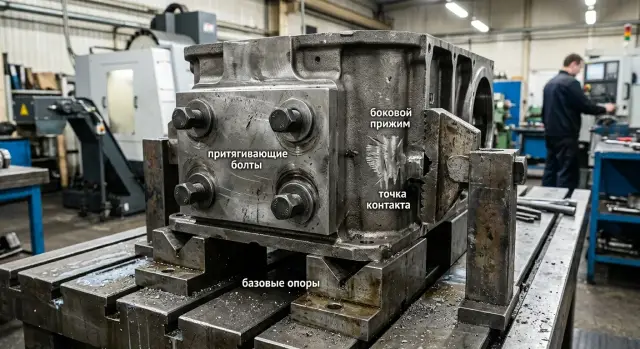
Housing Part Clamping: Bolts or Side Clamping?
Let’s look at when to use pull-down bolts and when a side stop is better, what marks a mistake leaves, and how to check a housing part’s clamping before production.
Why the part shifts already on the first clamp
The problem often starts before cutting even begins. The operator tightens the clamp, the force goes somewhere other than expected, and the housing does not seat against the bases — it shifts sideways or turns slightly.
This shows up especially fast on housing parts. Their support points are small, the walls may have different thicknesses, and the shape itself is rarely simple or rigid. If even one base does not touch fully, the part sits skewed. From the outside this is almost invisible, but after machining the size has already drifted by several hundredths or more.
A common cause is a thin wall. The operator tightens the bolt and feels that the part is already seated, but first the wall bends, and the housing still has not reached the support. The clamping scheme is already working incorrectly. When the clamp is released, the wall springs back and the geometry changes. That is why machining goes smoothly, without noise or vibration, but the size still does not hold.
On the machine, it usually looks like this: the housing rests on two supports, touches the third only by the edge, the side clamp applies force slightly above the center of rigidity, and the part turns just a little. The program runs normally, but the holes shift relative to the base, and the surface shows a twist after release.
Usually the cause is one of three:
- the clamp pulls the housing sideways instead of down toward the supports;
- the base is dirty or has a burr, so the housing does not seat fully;
- a wall or rib takes the load before the force reaches the rigid part of the component.
The worst case is when the first clamp seems quiet. Nothing creaks, the housing does not jump, and there are almost no obvious marks. But after machining you get size drift, uneven stock allowance on the sides, and marks at the contact points. That is a direct sign that the clamp acted before the part reached the correct position.
Bolts and side clamps: what is the difference
These methods follow different logic. A pull-down bolt draws the part toward the support plane, while a side clamp pushes it into the stop. On paper both options look reliable, but on the machine the difference becomes obvious very quickly.
A pull-down bolt is good at seating the part down if the supports are level and the area under the bolt does not deflect. But together with the downward motion, it can also pull the housing sideways. This happens when the surface is slightly uneven, chips remain under the part, or the bolt is not over a rigid zone. The part seems to creep across the supports by fractions of a millimeter, and that is already enough for scrap.
A side clamp works differently. It pushes the housing against the locating stop and often holds the size along the side base better. But if the clamp presses too high relative to the supports, it starts lifting the near edge. This is especially common on housings with a thin wall or a long overhang.
In simple terms: a bolt is better at seating the part onto the supports, while a side clamp is better at finishing it into the stop. At the same time, a bolt more often shifts the part along the plane, and a side clamp more often lifts the edge. Both options work poorly if the force goes through a thin wall.
That is why looking only at force is not enough. You need to understand where the force is directed and through which section of the housing it passes. If the load goes through a thick boss, rib, or shoulder, the setup usually behaves calmly. If the pressure falls on a thin wall, the part simply bends.
In practice, housing parts are often clamped with a combination of both. The bolt seats the blank on the supports, and the side clamp gently brings it into the stop. For a gearbox housing, cover, or cast blank, this is usually safer than trying to solve everything with one clamp. If you have to choose only one option, do not choose based on what is easier to clamp — choose based on where the housing can carry the load without bending or lateral shift.
What signs does incorrect clamping leave behind
Incorrect clamping rarely stays hidden for long. It almost always leaves marks either on the part itself or in the dimensions after machining.
The first signal is often visible on a rib or side wall. A narrow shiny strip appears, as if the part was lightly rubbed by metal. That is a shift mark: the housing did not settle calmly onto the supports, but moved sideways under clamping force.
The imprint of the clamp itself is just as telling. You expected contact in one zone, but the mark appeared higher, closer to the edge, or even on an area that was not supposed to work at all. That means the force is going somewhere else than intended, and the housing starts to twist or spring.
The most unpleasant sign appears during inspection. The tool was not changed, the program was not touched, but after reclamping the size drifted by several hundredths or more. Usually this means the part seats differently each time: in one case the bolt pulls it, in another the side clamp slightly twists the housing.
There are also less obvious signs:
- holes shift relative to the base plane;
- the surface looks flat after the pass, but changes position;
- one side of the housing gets a clear pressure mark while the opposite side stays almost clean;
- a local dent or slight tilt appears on a thin wall.
This is common on gearbox housings, covers, and parts with cavities. From the outside everything looks normal, but during assembly the holes no longer line up as they should.
A quick check is simple: apply a thin layer of marker or dye to the support points and the clamp contact area, clamp the part with partial force, then remove it and look at the marks. If the contact is symmetrical, the marks are where you expected them, and there is no shiny shift streak, the setup usually works. If one mark is strong, another is empty, and there is already a rub mark on the rib, it is better to move the support or shift the clamp point right away.
How to build the clamping setup
A good setup does not start with the clamp — it starts with the datums. If you first choose a convenient place for the bolt or clamp, the housing often sits crooked. Later this shows up in the size, in the support marks, and in constant adjustments on the machine.
For a housing part, the forces should go into rigid points and press the blank against clear supports. Usually this is the bottom face, a machined end face, or two mutually perpendicular surfaces that define the position without wobble.
-
First choose the datums that hold the shape of the part. Look not just for accessible surfaces, but for the ones from which the dimensions will later be measured. For a cast or welded housing, it is better to rely on dense and repeatable areas, not on a random protrusion or raw casting skin.
-
Then place the supports under rigid areas. Usually these are zones near ribs, bosses, thickened sections, and the solid bottom of the housing. If a support is placed under a thin wall, it will deflect even under moderate tightening.
-
After that, set the direction of force. Pull-down bolts should seat the part onto the supports, not pull the center down between them. A side clamp should push the housing into the stop so that it does not creep along the plate or twist.
-
Check tool access and chip removal right away. The clamp should not block the machining zone, interfere with tool changes, or trap chips under the base. Even a small chip under a support can easily cause a skew.
-
Finally, define the tightening order. First seat the housing onto the bases with light force, then bring it against the stops, and only after that apply the working tightening. If you tighten the fasteners in no particular order, the part often shifts at the very end.
A simple example: a housing has thin side walls and thick lower bosses. The supports are placed under the bosses, the side clamp is directed into a rigid stop, and the bolts are positioned closer to the supports rather than above an empty pocket. Such a setup usually behaves predictably from the very first installation.
Before the first part, it is useful to do a dry seating without cutting. Place the housing, tighten it in the chosen order, and check whether there is wobble, a gap at the supports, or clear movement into the stop. At this stage you usually catch mistakes that would otherwise cost the entire batch.
How to check the setup before starting a batch
A pre-series check takes only a few minutes and saves much more than that. If you skip it, scrap can run through the whole batch.
First, place the housing on the supports without force. Do not tighten the bolts and do not engage the side clamp. Just press the part by hand at two or three points and rock it slightly. If the housing wobbles, the supports were chosen poorly or one of them is higher than the others. In that state, tightening will not hold the geometry — it will only skew the part.
Next, tighten the clamps one by one. After each step, look at the base plane: has a gap appeared, has a corner lifted, has the housing shifted toward the stop? It is useful to shine a regular flashlight into the gap or run a feeler gauge along the base. If a feeler starts to slide in freely where it did not before tightening, one of the clamps is already moving the part.
A good quick test is the double clamp. Clamp the housing once, measure it at the preselected points, then fully release it and clamp it again in the same sequence. After that, repeat the same measurements. If the numbers differ noticeably, the problem is not the program and not the tool — it is the fixture setup itself.
You do not need a complicated measurement map for this test. Two or three points are enough, as long as they are easy to repeat: height from the base, distance to the side stop, and the position of one control hole or edge. The main thing is to measure the same places the same way both times.
A single trial cycle also tells you a lot. For example, the housing sits firmly on the supports, but after tightening the side clamp a feeler starts going under the far corner. After release and reclamping, the size from the base changes by several hundredths. That is an early sign that the clamp is not fixing the part — it is turning it.
Before a batch, a short sequence is useful:
- dry setup without cutting;
- one trial machining cycle;
- repeat clamping of the same part;
- comparison of one or two key dimensions and the contact marks.
If the size does not drift after reinstallation, the contact marks stay in the same places, and the clamps do not interfere with the tool, the setup is ready to work.
Where people most often make mistakes
Most problems start not with clamping force, but with the point where that force is applied. A part holds size only when the force goes into the support, not when it bends the housing itself.
A common mistake is placing the clamp too far from the support point. From above everything looks fine, but between the pressure point and the support there is a section that works like a lever. The housing springs slightly, and after the clamp is released the shape returns, which makes the size drift.
Another mistake is pressing on a cover, a thin wall, or the edge of a pocket instead of a rigid rib. The part seems clamped, but marks on the surface and variation across the plane quickly reveal the problem. If after the first pass you see an imprint, crushed coating, or a shiny spot on a thin wall, the clamp is in the wrong place.
With a side clamp, the miss is often even simpler. The operator first pulls the housing sideways and only then tries to seat it down onto the supports. That does not work well. The housing should first sit firmly on the base, and only then can it be pressed from the side. Otherwise the part hangs on an edge, and the height dimension starts behaving on its own.
These signs usually stand out:
- the part wobbles before clamping, but seems to straighten after clamping;
- after release, you can see a shift in the plane or at a hole;
- clamp jaws, shoes, or bolts leave marks on the wall;
- the operator keeps wanting to tighten more each time.
The urge to add more force is a separate classic mistake. If the supports are not enough, extra tightening will not save the situation. It only bends the housing and makes the result less predictable. Bolts do not fix the setup either in that case. They only press the part harder onto the same poor base.
Another mistake appears after the first part. The setup is slightly changed on the spot: a shoe is moved, a washer is added, the side clamp is loosened, and the work continues. But nobody records the result. A few hours later it is hard to tell which version produced the right size and which one just happened to work once.
If you had to change clamp points, record at least three things: where the support was, where the clamp pressed, and what changed in the size. A couple of short notes often save an entire shift.
What should be recorded before the batch
Before starting a batch, it is better to record the setup openly, not keep it in your head. One photo from above and one from the side are often more useful than long explanations at the machine. Mark the supports, stops, contact points, and the order in which the operator tightens the clamp.
This is especially useful for housing parts, because the mistake rarely looks big at the beginning. The part may shift only slightly, and later that shows up in the size, flatness, or concentricity. If the setup uses both a side clamp and pull-down bolts, note which one acts first and which one only finishes clamping after the part is seated on the base.
It is worth keeping one reference housing. Take the part on which you have already checked the dimensions, contact marks, and seating on the base, and keep it out of normal production flow. It is needed for a quick comparison after an operator change, a new batch of blanks, or a changeover.
Before launching a series, a short trial on several parts is useful:
- run 3-5 parts in a row on the same fixture;
- remove one part and clamp it again;
- compare the critical dimensions and contact marks;
- check whether the part position changes from the first to the last clamp.
Do not look only at the dimensions. Signs of incorrect clamping often appear before the control dimension goes out of tolerance. Warning signs are fresh dents near the edge, shiny streaks near the stop, an imprint from the clamp on the side, or a skewed contact mark under the bolt. If the first part shows one mark and the fourth part shows a different one, it is better to stop and correct the setup immediately.
A useful habit is to write a short operating order on a marker tag or a card next to the fixture. The operator should not have to remember what to use first to seat the part on the base and what only serves to hold it.
If you are choosing a machine for metalworking, fixtures, or preparing to launch a production line, EAST CNC can help with equipment selection, commissioning, and service support. In this kind of work, general advice is not enough — usually the real part, its datums, and the clamping method decide everything.
FAQ
Why does a housing part move already on the first clamp?
Most often the part shifts not because of cutting, but because of how it sits in the fixture. The clamp pulls the housing not toward the supports, but sideways or slightly twists it, and the part immediately ends up in the wrong position. Another common cause is a dirty base, a burr, or a thin wall under load. You may barely notice it from the outside, but once the clamp is released, the geometry changes.
Which causes more shift: a bolt or a side clamp?
A pull-down bolt usually seats the part downward onto the supports better, but it can also pull it across the surface. A side clamp, on the other hand, is better at pushing the housing into the stop, but it can lift the edge if it presses too high. If you have to choose between them, do not focus on convenience — focus on the rigid area of the part. The force should go through a rib, boss, or thick pad, not through a thin wall.
How can I tell whether the problem is in the clamp and not in the program?
First rule out the obvious: do not change the program or the tool, and clamp the same part twice. Clamp it, measure several points, then fully release it and clamp it again in the same sequence. If the numbers differ, the problem is almost certainly in the fixture setup. When the clamp is the cause, the part sits a little differently each time.
Where is the best place to put supports on a housing part?
Place the supports under the rigid areas of the housing. Usually these are zones near ribs, bosses, thickened sections, and the solid base of the part, where it can carry load without noticeable deflection. Do not place a support under a thin wall or over an open pocket. There the housing bends first and only then seats, so the size starts to drift.
Can a clamp press on a thin wall?
It is better not to clamp a thin wall. A thin wall bends easily even before the force reaches the rigid part of the component, and after release the shape returns somewhere else than it was during machining. If there is no other option, reduce the load and move the clamp point closer to the rigid zone. But in a normal setup, it is safer to press through a rib, boss, or thick pad.
What is the best order for tightening clamps?
First seat the housing on the bases with light force. Then gently bring it into the stop, and only after that apply the working tightening. If you tighten the fasteners in random order or too hard right away, the part often shifts at the very end. That is how the housing ends up tightly clamped, but the size has already moved.
How can I quickly check the fixture setup before starting a batch?
Do a dry setup without cutting. Place the housing on the supports, gently rock it by hand, and check whether there is any wobble or a gap at the base. Then tighten the clamps one by one and check the gap with a feeler gauge or a flashlight. After that, perform a double clamp and compare two or three simple dimensions. This test quickly shows whether the seating repeats or not.
What marks on the part indicate incorrect clamping?
The marks usually reveal the direction of the mistake. A narrow shiny streak on a rib or wall usually means a shift across the surface, while an imprint from the clamp near the edge shows that the force went through the wrong area. If the contact spots change after reclamping, the setup is unstable. In that case, it is better to move the support or shift the clamp point right away.
When is it better to combine bolts and a side clamp?
A combined setup often behaves more calmly on housing parts. The bolt helps seat the blank on the supports, and the side clamp gently brings it into the stop. This approach is convenient for covers, gearbox housings, and cast blanks where one clamp rarely solves everything at once. The main thing is not to press through a weak wall with both clamping methods.
What should be recorded before starting a batch?
Keep the setup as simple as possible: where the supports are, where the clamps press, and in what order the operator tightens the hardware. One clear note or a couple of photos usually saves a lot of confusion between shifts. It is also useful to keep a reference part with a verified fit. It makes it much easier to quickly see whether the setup has changed after a changeover and a new batch of blanks.