Chamfers and Radii on a Turned Part Without Shop-Floor Edits
Chamfers and radii on a turned part can be set so that insert changes and wear compensation stay in the program, not as manual edits at the machine.
Why manual edits appear
Manual edits almost always start with one simple thing: the program stayed the same, but the tool did not. The operator changed the insert, adjusted the overhang a little, corrected the tool height, and the machine followed the same path with a different actual cutting point. Diameter size can still be brought back quickly with an offset, but a chamfer or a radius changes right away.
This is especially noticeable when chamfers and radii on a turned part depend on the exact position of the insert tip. On the drawing everything is simple: 1 x 45°, R2, a smooth transition. On the machine, even a small difference at the tool tip changes the contact point, and the part geometry no longer matches what was built into the program.
The problem grows when the operator edits the tool path itself instead of the wear offset. He shifts the end point, changes a coordinate, adds an extra line to save the current part quickly. Once this helps. After the next insert change, the same program starts producing a different chamfer because the code now contains a one-off adjustment for old wear.
With a chamfer, this shows up immediately. Suppose that after replacing the insert, the 1 x 45° chamfer became shorter. If the operator moves the path manually, he is matching the result to the current tool. But the new insert may sit slightly differently, and the same adjustment will give an overshoot or an undershoot.
With a radius, the situation is worse. Tip wear changes not only the size, but also the transition between lines. The radius starts to "drift": somewhere it becomes sharper, somewhere a step appears, and sometimes the part looks fine to the eye but fails inspection with a template or in the fit.
Manual edits usually appear for four reasons:
- after a change, the tool cuts from a different point;
- the operator fixes the problem in the code instead of in the offset;
- the chamfer depends strongly on the exact X and Z intersection;
- tip wear affects radii and tangent transitions the fastest.
In practice it looks like this: the first two parts are fine, then the insert wears a little, the operator shifts the program, the next batch is adjusted again, and in a week nobody understands which size is held by the code and which one survives only thanks to random tweaks. If the part contour lives separately and tool wear is kept in offsets, there are far fewer such failures.
Separate the part contour from tool corrections
When the program stores the clean part geometry, setup becomes calmer. The operator sees the drawing dimensions, not the traces of past adjustments made for a specific insert or for random wear.
This is especially noticeable where there are chamfers and radii on a turned part. If you once "fixed" the contour itself and then shifted it again after an insert change, after a couple of runs it becomes hard to tell what is nominal and what is a temporary measure.
A good setup is simple: the program defines only what should end up on the part. All small shifts caused by wear, regrinding, or the features of the current insert are entered in the tool offsets.
That gives you two separate layers. The first layer is the drawing dimensions. The second is the corrections for the real tool, which can be changed without rewriting the path.
In practice it looks like this:
- the part contour is programmed to nominal dimensions;
- X and Z wear are kept in the offsets;
- the insert tip radius is set in the tool data, not used to "draw" the part size;
- after each setup, record exactly what was changed.
The last point is often underestimated. If the operator reduced X wear by 0.03 mm, that should be recorded immediately. Otherwise the next shift will start with guesses instead of a clear baseline.
Imagine a simple part: an outside diameter, a faced end, a 1x45 chamfer, and a small transition radius. After the first part, the size drifted by 0.02 mm on diameter. The right action is to apply a correction in the X offset. The wrong action is to change the diameter dimension in the program itself. In the second case, the contour no longer matches the drawing.
The same logic applies after an insert change. If you installed a new insert of the same type, the program usually does not need the part geometry rewritten. In most cases, it is enough to update wear compensation and check the first pass.
On machines used for series production, this approach saves not minutes but hours per month. There are fewer mistakes, restarting is easier, and finding the cause of scrap does not turn into sorting through someone else’s edits in the code.
How to set up the program step by step
If you want to avoid manual edits at the machine, do not mix part geometry and tool corrections in one logic. The program should describe the contour itself, while the offset should account for the real cutting tool and its wear. Then after an insert change you do not rewrite the part dimensions.
First, choose one reference and stick to it until the end. On a turned part this is usually the face and the X axis, and all dimensions are set from them. If some dimensions on the drawing are taken from another shoulder, it is better to convert them into one system right away. Otherwise a 1 x 45° chamfer and an R0.8 radius can start to drift already during input.
Working sequence
- Rewrite all contour elements from the drawing in one order: cylinders, faces, grooves, chamfers, radii.
- Mark where a straight section ends and where the transition begins. This removes extra guesswork when writing the path.
- Build a clean part contour without temporary allowances, eyeballed adjustments, or local X or Z shifts.
- Assign the working cutting tool a separate geometry offset and a separate wear offset, if your control supports it.
- Run a dry cycle and check not only the sizes but also the transition between the line, chamfer, and radius.
At this stage many people rush and immediately edit the program blocks. That is a bad habit. If the tool shows a deviation after the first part, change the offset, not the contour. That way you keep the program logic and preserve the original geometry.
It helps to keep a small table next to the program: tool number, insert tip, nose radius, offset, part material. In series work, this saves time. The operator can see what changed after an insert change and does not have to look for the cause in the chamfer or radius.
On a simple part, it looks like this: first you describe all diameters and faces, then you add the transitions, and only after startup do you check whether the actual size matches the drawing. If you need to remove another 0.02 mm on diameter, you change the tool wear. The part contour stays the same.
How to program chamfers
A chamfer is better programmed as part of the part geometry, not produced manually by feed and stop. When the operator "catches" the size at the machine, the same part can come out differently in the morning and in the evening. The program should know in advance where the chamfer starts and where it ends.
Base it on the part dimension, not on the operator’s habit. If the drawing calls for a 2x45° chamfer, the program should define two points on the nominal contour and connect them with a straight line. Then the size stays predictable, and chamfers and radii on the turned part do not depend on who is standing at the machine.
Simple example: outside diameter X30 and face Z0, chamfer 2x45°. If the machine works in diameter mode on the X axis, the points will be X30 Z-2 and X26 Z0. Many people make the mistake right here and take off a diameter on X instead of a radius. As a result, the chamfer comes out larger than needed.
Before calculating the tool path, check three things:
- what insert angle you have
- whether the X axis is programmed in radii or diameters
- how the control defines the chamfer: by a separate command or through the end points
It is better to check the insert angle in advance, even if the chamfer seems simple. In theory, 45° can be achieved with different inserts, but in real cutting the tip shape and holder position change the result. If the tool angle is wrong, the program will only be correct on the screen.
Another common mistake is to edit the contour itself after an insert change. Do not do that. The contour should remain nominal, and any changes after a tool change or due to wear should go into the tool offset. Then you do not have to rewrite the program after every cutting edge change.
This is especially noticeable on series parts. Today you installed a new insert, tomorrow the tip wore a little, and a week later the material batch changed. If the chamfer is built into the geometry correctly, the operator changes wear compensation in a minute and keeps running without manual edits at the machine.
How to program radii
A radius is better programmed as part of the full part profile. Do not draw it as a separate "manual" arc that later has to be chased with machine correction. If the line, the radius, and the next line are built into one clean contour, the program moves the tool predictably and the size does not drift after an insert change.
Most often, the failure starts not at the radius itself, but at the tangency point with the adjacent sections. If the straight line before the radius or after it ends where it should not touch the arc, the machine will still run the path, but the part will get a kink, a step, or an oval shape. So check not only the R value, but also the start and end coordinates of the arc.
In practice, a simple approach helps: first define the two straight lines between which the radius should lie, then check that the arc touches them without a gap. Even a tiny X or Z error quickly creates scrap, especially on short transitions.
There is another common limit. The minimum radius on the part must match the insert geometry. If the insert tip is larger than the programmed radius, the tool physically cannot reproduce the profile exactly as in the program. Then the operator starts adjusting wear, shifting the size, and loses the logic of compensation. This is especially noticeable when chamfers and radii on a turned part are made in one area and a clean transition without manual finishing is expected.
Treat tip wear separately from the part size. Do not try to correct both the diameter and the radius with one compensation. That can easily ruin the neighboring section of the profile. It is better to keep the contour geometry in the program and the tip wear in its own correction, so after an insert change you only change what has actually changed.
After the first part, measure the radius at one specific point and compare it with the expected shape. There is no need to remeasure the whole contour right away. If the tangency point is clean, the transition is smooth, and the radius matches the template or measurement, the program usually runs steadily from there. This saves time and removes the habit of "tweaking by eye" at the machine.
Example on a simple part
Let us take a shaft made from bar stock. It has a 40 mm diameter, then a step down to 30 mm, a 1x45 chamfer is needed on the entry edge, and an R2 radius is required in the transition to the step. It is a simple part, but these are exactly the parts where manual edits at the machine appear most often.
If the program is built carefully, it stores only the nominal part contour. The chamfer, radius, diameters, and lengths are set from the drawing. Corrections for the actual cutting tool are kept separately, in wear compensation.
During the first setup, the operator sets the tool, machines a trial part, and checks the dimensions. Suppose the step diameter came out 0.04 mm too large. Instead of editing coordinates, he changes only the X wear to the needed value and runs a repeat pass. The part contour does not change, so the 1x45 chamfer and the R2 radius stay where they should be.
In practice the scheme is simple:
- the contour is programmed once from the drawing
- tool wear is handled in compensation
- after an insert change, only the compensation is adjusted
Now imagine the next shift. The operator installs a new insert, and the tool cuts a little differently. The size, for example, drifts by 0.03 mm. If the contour has already been filled with manual tweaks, he will again have to figure out which points were moved before and why. If the contour is clean, he simply enters a new wear correction and gets the same result without rewriting the program.
That is how chamfers and radii on a turned part start to repeat from part to part. The operator does not need to chase the size on the chamfer edge again or recalculate the R2 transition. He checks the diameter, the length, and, if needed, slightly adjusts only the X or Z compensation.
The difference is already clear on a small batch. Setup goes faster, the program stays understandable, and an insert change does not turn into a new contour setup. For the shop, that means one simple thing: dimensions repeat, and time is not lost on local touch-ups.
Where people most often make mistakes
When chamfers and radii on a turned part vary from part to part, the reason is often not the machine, but the logic of the corrections. The most expensive mistake in terms of time is simple: tool wear is entered directly into the profile coordinates.
At first, this seems convenient. The size is back in tolerance, the part moves on. But after an insert change nobody remembers where the clean geometry ends and where the temporary correction begins. In the end the same program cuts differently, and the programmer and setup operator look for the cause in the wrong place.
Insert wear compensation should live in the offset table, not in the contour. If you change X or Z for the sake of one chamfer, it is easy to shift the neighboring shoulder or fit.
People also often get the direction of compensation wrong. The tool approaches the part from the other side, but the program or the table still keeps the old logic. On screen the path looks similar, but on the part the chamfer becomes shorter, the radius breaks, and the transition stops being tangent.
Another trap is confusing the theoretical tip with the real insert geometry. The CNC system calculates the path based on the offset data: insert type, nose radius, and cutting edge position. If the wrong value is entered there, the machine will faithfully calculate the wrong transition between the straight line and the arc.
This is easy to see in a simple situation. The operator wants to restore the diameter and adds 0.02 mm of wear without checking the nose radius. The diameter is almost right, but the R1 radius on the adjacent transition is no longer correct. Then he adjusts the end of the chamfer as well, and the error only grows.
Old offsets left from the previous batch also often ruin startup. The material is different, the insert is new, but yesterday’s values are still in the table. The first part is close to size, but then a chain of small corrections begins, and the program loses predictability.
A good habit here is simple:
- before a new batch, zero out or verify wear offsets
- keep the nominal contour free of temporary tweaks
- check the tool approach side after changing the holder or insert
- verify the nose radius and insert type in the offset
- do not fix one size by manually changing several neighboring coordinates
The worst mistake is fixing one size and ruining the next transition. A chamfer and a radius are almost always tied to the adjacent surfaces. If another element changed after the correction, it is better to roll the coordinates back and check the offset than to keep editing the contour by hand.
Quick check before starting
One short look at the program often saves more time than searching for the cause of scrap at the machine later. If the contour in the code differs from the drawing even a little, no wear compensation will save the entire size.
First, verify the geometry itself. The coordinates of the straight sections, the chamfer start points, and the center or end points of the radius must match the drawing, not the way the part is "usually made" in the shop. This is especially important if chamfers and radii on a turned part affect not only appearance, but also fit or assembly.
Then look at the tool. The program should be linked to the exact offset you will use to machine the part, with no confusion between nearby turret positions. The mistake here is frustrating: the path looks correct, and the size shifts already on the first part.
It is useful to go through five points:
- the program contour matches the drawing in diameters and lengths;
- the offset number is linked to the correct tool and insert;
- the chamfer does not eat extra length and stays within tolerance;
- the radius touches the straight sections smoothly, without a break in the transition;
- the trial part gives sizes that can be measured easily with calipers or a micrometer.
Chamfers are most often missed on the Z axis. For example, a 1x45° chamfer may look fine, but take an extra 0.2 mm off the face length. This is easy to miss in a quick review, but by the time the finished batch is made, it is too late.
Radii have another typical mistake. The program builds the arc, but there is a barely visible kink at the joint with the straight line. The eye does not always catch it on the screen, but on the part it shows up right away after the pass, especially on a finished surface. If the transition is not tangent, it is better to correct the two control points before startup instead of polishing the problem with compensation.
Make the trial part so that after the first cycle you get clear measuring points. A good sign is when you can separately check the diameter, the length to the chamfer, and the radius itself, rather than guessing from one overall mark. Then the next correction will be precise: change tool wear or the size shift, instead of rewriting the contour right at the machine.
What to do next
After the first successful run, do not leave the program as is. If chamfers and radii on the turned part came out without shop-floor touch-ups, you already have a working method, and it is worth locking it in.
Save the program as a template for similar parts. It is better to keep together not only the contour itself, but also the rules you use: where you define the chamfer, where the radius goes, how you name the tool correction, and which approach and retract moves you use. In a month, that will save more time than it seems.
Also keep separate notes on the dimensions that drift first with wear. Most often these are the outside diameter, the facing length, and the small transitions where the error is immediately visible on the chamfer or radius. If such notes accumulate over several batches, the setup operator already knows where to look first, and the operator does not touch everything at once.
You can establish a simple routine:
- save the successful program in a templates folder;
- record the dimensions that change first;
- note which tool and which insert were installed during the stable run;
- label the inspection points after the first pass and after finishing.
Another useful step is to agree in advance with the setup operator on which dimensions to check first. On a simple bushing, two diameters, the shoulder length, and one radius after finishing are often enough. This kind of inspection takes less time and shows faster whether the issue is wear or a geometry error in the program.
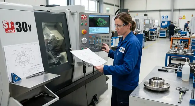
If you are choosing a new lathe for this kind of work, look at more than just power and machining size. Check how easy it is to manage wear compensation, store repeatable programs, and return quickly to a stable mode after an insert change. At EAST CNC, you can discuss model selection, commissioning, and service support for this kind of work. That is especially useful when you have a series of similar parts and every extra edit at the machine slows production down.